





 English
 русский
When a cardan shaft begins to vibrate or the bearing temperature climbs unexpectedly, the first area to examine is alignment. In many field service reports, the root cause is not a defective component but a driveline that was installed without correcting the angular relationship between the driving and driven shafts. Getting alignment right is not an optional refinement; it is the single most effective way to keep the universal joints, support bearings, and driven equipment working within their designed load envelope.
Content
What Is Cardan Shaft Alignment?
A cardan shaft, also known as a universal drive shaft or cross-shaft assembly, transmits torque between two shafts whose axes are not collinear. In a typical configuration, a cross-shaft universal joint is mounted at each end of the shaft, allowing the connected machinery to accommodate misalignment and relative motion. Cardan shaft alignment is the process of setting the angular and positional relationship between the input and output shafts so that the universal joints operate at their intended angles, with equal angles on both ends and with proper phasing.
Unlike a rigid coupling where the goal is to bring two shaft axes into perfect coincidence, a cardan shaft is designed to work with deliberate angularity. The alignment procedure is therefore about controlling the amount and distribution of that angularity rather than attempting to eliminate it completely. When the angles are unequal or the joints are out of phase, the output speed of the driven shaft fluctuates within each revolution. That fluctuation creates torsional vibration, dynamic loading on the bearings, and accelerated wear of the joint components.
Why Cardan Shaft Alignment Differs from Conventional Shaft Alignment
In standard shaft alignment for a direct-coupled or spacer-coupled machine, the goal is to achieve zero parallel offset and zero angular misalignment at the coupling faces. The acceptance limits are usually expressed in small geometric values, and the check is performed on the shaft ends themselves. With a cardan shaft, the measurement strategy changes because the coupling is not a fixed mechanical link; it is a jointed connection that relies on angle to function.
The table below summarizes the key differences between conventional alignment and cardan shaft alignment, helping you identify why the methods and tolerances cannot be swapped between the two.
| Aspect | Conventional Shaft Alignment | Cardan Shaft Alignment |
|---|---|---|
| Primary goal | Zero offset and zero angle at coupling faces | Equal joint angles and correct phasing |
| Measurement location | Coupling faces or shaft ends | Joint positions and shaft centerlines |
| Critical error | Parallel offset | Unequal joint angles |
| Effect of failure | Bearing loads and seal wear | Torsional vibration and joint wear |
| Typical tooling | Dial indicators, laser systems | Specialized brackets, angle measurement |
Common Cardan Shaft Alignment Errors
Even experienced mechanics can miss the subtle conditions that cause premature cardan shaft failure. The following errors are the most frequently observed on industrial drivelines and each has a distinct impact on service life.
Angular and Compound Angle Errors
A single universal joint transmits constant speed only when the joint angle is zero. When an angle is present, the driven shaft speed varies twice per revolution, with the magnitude of variation growing as the angle increases. In a cardan shaft with two joints, this speed fluctuation is canceled only when the input and output joint angles are equal and the joints are in phase. If one joint is set to 3 degrees and the other to 5 degrees, the output speed oscillation does not cancel. The residual torsional vibration will then be transmitted into the gearbox and driven machine.
Parallel Offset between the Connected Shafts
Parallel offset, or a lateral distance between the input and output shaft centers, forces the cardan shaft to operate with an additional bending condition. This is particularly damaging when the shaft has to work near its maximum length or when the support bearings are not designed for heavy side loads. In practical terms, a small parallel offset is often acceptable as long as the resulting joint angles stay within the design limit, but the combined effect can push the system into resonance.
Phasing Issues
Phasing refers to the angular orientation of the two universal joints relative to each other. For a two-joint cardan shaft to transmit constant velocity, the yokes at the ends must be oriented with their cross pins in parallel planes. If a maintenance crew reassembles the shaft without marking the original position, a phase error of even a few degrees will produce a noticeable roughness and will significantly reduce the life of the universal joint cross pins.
Bearing and Gearbox Loading Effects
Misaligned cardan shafts do not just damage themselves. The fluctuating torque and shaft deflection create axial and radial loads that propagate into the support bearings and the connected gearbox. In severe cases, the input bearing of a gearbox can fail after a few hundred hours of operation, even though the gearbox itself was correctly mounted. The root cause is usually found upstream in the driveline alignment.
How to Align a Cardan Shaft Step by Step
The procedure below is a practical field method that works for most heavy industrial applications. It assumes that the shaft is installed and that the support bearings or flange positions are adjustable.
- Lock the machine in a known position and ensure that the input and output shafts are in the same vertical plane where possible. Mark the relative position of the yokes before any work is performed.
- Measure the runout of the input and output shafts at the mounting flanges using a dial indicator. This establishes whether any parallel offset exists. Record the values at the top, bottom, left, and right positions.
- Measure the angularity of the cardan shaft itself by comparing the angles of the two shaft centerlines. In many cases, you can use an angle gauge on the flanges or the shaft body to get a reliable reading.
- Adjust the support feet or motor position to bring the two joint angles as close to equal as possible. If the equipment has a fixed center distance, use shims on the support bearing to achieve the required equalization.
- Verify phasing by checking the yoke orientation. The cross pin of the input yoke must be parallel to the cross pin of the output yoke. If not, rotate one end of the cardan shaft together with its flange until the yokes are aligned.
- Run the machine at its normal speed and monitor vibration levels. Compare the vibration signature with the baseline. Continue fine adjustment until the vibration amplitude stabilizes within the accepted range.
Because cardan shafts are often used in confined spaces, a full alignment check can be difficult without disassembling the shaft. In some cases, a partial removal of the shaft is required to access the flanges, but the key is to measure the angles accurately and then relay the data to the installation process.
Selecting the Right Cardan Shaft for Aligned Drives
The geometry, length, and joint type of the cardan shaft have a direct influence on how much misalignment can be tolerated and how easily the alignment can be achieved. For industrial applications where angularity and torque are both significant, the standard SWC series of cross-shaft universal joint couplings offers a practical balance between load capacity, length compensation, and ease of alignment.
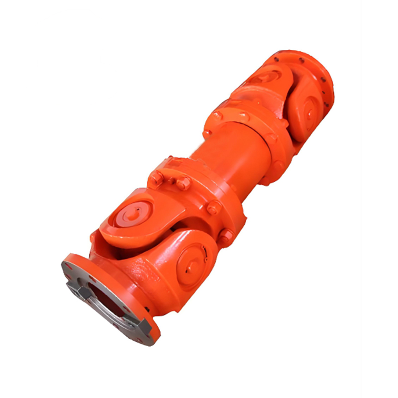 Large-Scale Telescoping Flange Cross-Shaft Universal JointDesigned for large-scale installations with fixed connection distances, this flange-type joint offers telescoping axial movement to ease alignment and reduce precise positioning needs.View Product →
This flange-type telescoping universal joint is designed for large-scale installations where the connection points are spaced at a fixed distance but still require some angular adjustment. The telescoping feature allows axial movement, which simplifies the installation procedure and reduces the need for exact axial positioning during alignment.
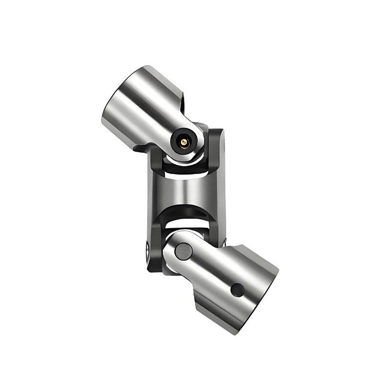 Precision Double-Type Universal Shaft for Large AnglesProvides high transmission accuracy for applications with large working angles, featuring precision bearings for consistent angular velocity over extended service.View Product →
For applications where a larger working angle is unavoidable, the precision double-type universal shaft provides a higher transmission accuracy and is often used on test benches and specialized equipment where consistent angular velocity is critical. Choosing a shaft with precision-bearing quality helps maintain the intended geometry over a longer service period.
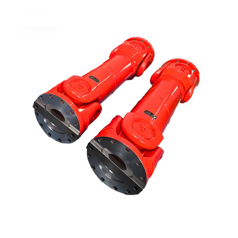 Standard Extension Universal Joint Coupling with Welded FlangeThis welded-type extension joint offers a rigid base for heavy transport and construction machinery, tolerating angular misalignment and side loads during peak torque.View Product →
The welding-type extension design in the SWC-BH series is common in heavy transport and construction machinery where the cardan shaft is expected to tolerate both angular misalignment and some degree of side load. During alignment, the soldered flange construction provides a rigid base that holds its geometry even after the torque loads reach their peak.
When selecting a cardan shaft, the alignment budget should be one of the selection parameters. If the connected equipment is expected to settle or move over time, a shaft with greater angle capacity and integral length compensation will reduce the frequency of re-alignment. This is especially true for mobile equipment, where frame flexing can change the alignment condition during operation.
Practical Considerations and Final Advice
The most reliable way to protect a cardan shaft driveline is to treat alignment as an intervention that must be verified after installation, after any maintenance that moves the connected machinery, and after a period of thermal cycling. The recommended interval for checking alignment on a heavy industrial mill is typically six to twelve months depending on the equipment duty cycle.
If the machine shows signs of noise, vibration, or uneven temperature rise, a quick check of the cardan shaft angle and phasing should be the first diagnostic step. A routine inspection that only checks the tightening of the bolts is not sufficient, because the actual loaded operating angles may be different from the static installed positions.
For additional background on how coupling design affects drive system reliability, consider our technical article on heavy-duty drive systems that explains the working principles of alternative shaft connections. This background is useful when deciding whether a cardan shaft or another type of coupling is the most appropriate solution for your application.