


 English
 русский
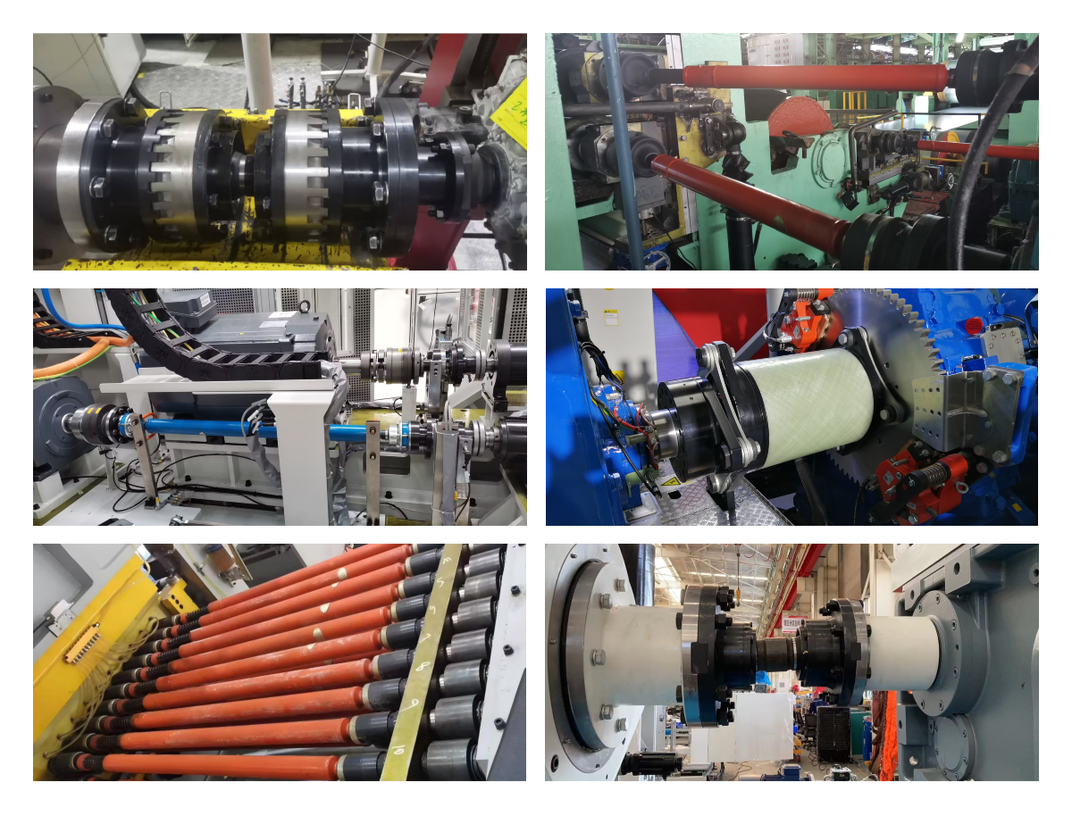
Industrial CV (Constant Velocity) joints transfer high torque and rotational motion between misaligned shafts while eliminating speed fluctuations, vibration, and noise, crucial for industrial, agricultural, and heavy machinery. They offer smooth power transmission in steel mills, food machinery, paper mills, and pump systems, replacing traditional gear or cross-shaft couplings to improve performance.
1.Key Features & Advantages in Industrial Applications
Constant Velocity: Unlike Cardan joints, CV joints operate at a true constant velocity, preventing vibration and torque fluctuations, particularly with unequal angles.
High Misalignment Capabilities: Accommodate significant angular misalignments and, in some cases, axial movement.
Long Life and Low Maintenance: Designed to reduce vibration-related damage in heavy equipment, such as steelmaking and rolling mills.
High Efficiency: High-efficiency types, offer low sliding resistance and reduced heat generation.
Common Industrial CV Joint Types
Fixed Joints: Suitable for large steering angles and fixed positions.
Sliding/Plunging Joints: Feature low sliding friction and are ideal for axial movement.
CON-VELRJoints: Known for handling heavy loads and providing pure constant velocity for industrial machinery.
2.Primary Applications
Steel Industry: Continuous casting, hot/cold rolling mills, and levelers.
Material Handling: Conveyors, cranes, and heavy-duty drivetrains.
Specialty Machinery: Food processing, medical devices, and agricultural equipment.
Pumps and Compressors: Industrial blower and pump drives.
3.Selection Guide
Selection is highly specialized and typically requires in-depth consultation with the manufacturer:
Operating Angle: Determine the maximum fixed operating angle and the range of angular variation. This is the primary selection criterion.
Torque & Speed: Rated and peak torque must meet requirements. Operating speed must remain within allowable limits.
Axial Displacement Compensation: Determine whether the application requires fixed (Rzeppa) or plunging (Birfield) capability.
Installation Space & Interfaces: Confirm connection types on both ends (splines, flanges, keyways, etc.) and overall assembly dimensions.
Environment & Sealing: Select appropriate protective boot materials and grease with the required protection rating based on environmental conditions (temperature, dust, moisture).
4.Installation, Maintenance & Failure Modes
Installation: Must be performed with extreme care to avoid damaging precision raceways and steel balls. Do not strike. Typically requires press-fitting with specialized tools. Ensure the protective boot is correctly installed and securely clamped, and fill with specified grease type and quantity.
Maintenance: Regularly inspect the protective boot for damage, aging, or grease leakage. This is the most critical preventive maintenance measure. Periodically replace the grease (by qualified service personnel) based on operating hours or mileage.
Common Failure Modes:
Damaged Protective Boot → Grease Leakage/Contamination → Wear & Noise → Seizure or Fracture. (Most common cause.)
Overload → Pitting or spalling of steel balls or raceways.
Prolonged operation at extreme angles → Cage fracture.