





 English
 русский
Every rotating machine that transfers power between two shafts needs a coupling — a mechanical device that connects the shafts, transmits torque, and manages the inevitable small misalignments that occur in real-world installations. Gear couplings are among the most capable and widely deployed of all shaft coupling types, trusted in steel mills, mining equipment, turbines, and heavy industrial drives precisely because they combine high torque capacity with meaningful misalignment tolerance. Understanding how gear couplings work, how they compare to other shaft coupling types, and how to select the right coupling for a given application is the foundation of sound drivetrain engineering.
Content
What Is a Shaft Coupling?
A shaft coupling is a mechanical component that connects two rotating shafts end-to-end to transmit torque and rotational motion from a driving shaft (connected to a motor or engine) to a driven shaft (connected to a pump, gearbox, compressor, or other load). This basic function — torque transmission — is the coupling's primary job, but it rarely works alone.
In practice, shaft couplings perform three distinct roles simultaneously. First, they transmit torque and power between shafts that may be running at different speeds or loads. Second, they accommodate shaft misalignment — the angular, parallel, and axial deviations that occur between driver and driven shafts due to manufacturing tolerances, thermal expansion, foundation settlement, and assembly error. Third, they protect connected equipment by absorbing shock loads, damping vibration, and in some designs, acting as a mechanical fuse that fails before the more expensive components (motors, gearboxes, pumps) are damaged.
No shaft coupling perfectly satisfies all three requirements simultaneously. The selection process always involves trade-offs between torque capacity, misalignment tolerance, torsional stiffness, maintenance requirements, and cost.
The Main Categories of Shaft Couplings
Shaft couplings divide into two fundamental categories based on how they handle misalignment and shock.
Rigid couplings connect shafts with zero flexibility — they transmit torque with no accommodation for misalignment. This makes them appropriate only where shafts are precisely aligned and expected to remain so, such as in some bearing-supported vertical pump applications. Any misalignment in a rigidly coupled system transmits directly as bending stress into the connected shafts and bearings, accelerating wear and potentially causing early failure.
Flexible couplings are far more common in industrial practice and are themselves divided into two families. Mechanically flexible couplings achieve their flexibility through loose-fitting, sliding, or rolling mechanical elements — gear couplings, chain couplings, and grid (serpentine spring) couplings all fall into this category. Materially flexible couplings achieve flexibility through the elastic deformation of a compliant element — jaw (spider) couplings, tire couplings, diaphragm couplings, beam couplings, and bellows couplings are examples. Each family has different performance characteristics in terms of torque capacity, misalignment range, torsional stiffness, vibration damping, and maintenance needs.
What Is a Gear Coupling?
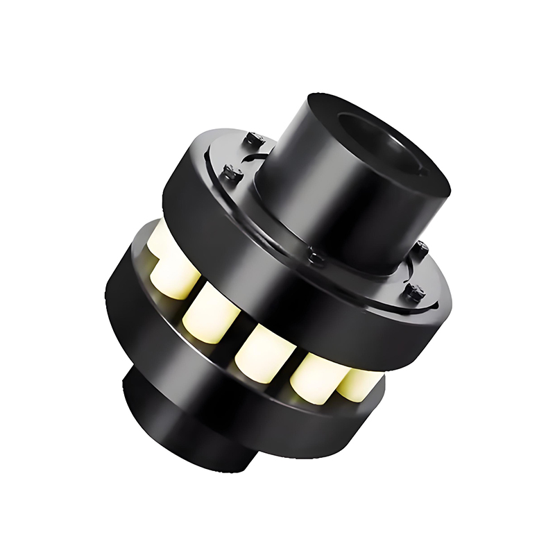
A gear coupling is a mechanically flexible shaft coupling that transmits torque through the meshing of external gear teeth on hubs with internal gear teeth on flanged sleeves. The standard configuration consists of two hubs — one mounted on each shaft — each carrying a set of crowned external gear teeth. These hubs mesh with two internally splined flanged sleeves that are bolted together at their flanges to form a rigid outer housing. Torque flows from the driving shaft through its hub's external teeth, into the sleeve's internal teeth, across the bolted flange connection, and out through the driven hub and shaft.
The mechanical flexibility of a gear coupling comes entirely from the rocking and sliding motion of the crowned external gear teeth against the internal sleeve teeth. As the shafts deviate from perfect alignment, the gear teeth shift their contact position within the sleeve rather than transmitting that misalignment as a bending load into the shafts. This sliding action requires lubrication — grease or oil — to prevent wear at the tooth contact faces, making gear couplings periodic-maintenance components rather than maintenance-free designs.
Gear couplings for high-torque industrial applications are the standard choice wherever maximum torque density — the highest torque capacity relative to coupling diameter — is the primary selection criterion, combined with a requirement to handle meaningful shaft misalignment.
Standard vs Drum (Crowned) Gear Teeth
The distinction between standard straight gear teeth and crowned (drum) gear teeth is critical to understanding gear coupling performance. Early gear couplings used straight-cut external teeth on the hub — cylindrical teeth with no curvature along their length. These transmit torque effectively but tolerate only very small angular misalignment before edge loading develops at the tooth contact, concentrating stress at one end of the tooth face and accelerating wear.
Crowned gear teeth — also called drum gear teeth — have a convex profile along the tooth length, with the tooth face curved so that its midpoint is slightly larger in diameter than its edges. When the hub tilts relative to the sleeve under angular misalignment, the crowned tooth rocks on its curved surface and maintains a more uniform contact distribution across the full face rather than concentrating stress at one edge. This geometry allows crowned gear couplings to accommodate significantly larger angular misalignment — typically up to 1.5° per gear mesh, compared to fractions of a degree for straight-tooth designs — while maintaining acceptable tooth surface pressure and service life.
The center of the crowned tooth's sphere is positioned on the shaft axis, and the tooth clearance is intentionally slightly larger than in straight-tooth designs. This combination of geometry and clearance is what enables the greater angular displacement capacity that makes drum gear couplings the preferred type for most modern industrial applications where shaft misalignment cannot be fully eliminated at installation.
Torque Capacity and Misalignment Tolerance
Gear couplings transmit the highest torque of any flexible coupling type for a given outer diameter. This torque density advantage is a direct result of the gear tooth engagement mechanism: multiple teeth share the load simultaneously across a relatively large contact area, distributing stress efficiently. Where an elastomeric jaw coupling or beam coupling of the same diameter might be rated to a few hundred Newton-meters, a gear coupling of identical outer diameter may handle several thousand Newton-meters — a factor of ten or more difference in torque capacity.
Misalignment tolerance in gear couplings covers all three types of shaft deviation. Angular misalignment — where the shaft centerlines intersect at an angle — is accommodated by the rocking action of crowned teeth; typical values are 0.5° to 1.5° per flex point, with two flex points per coupling (one at each hub-sleeve interface). Axial displacement — where one shaft moves along its own axis relative to the other — is accommodated by the sliding of the hub within the sleeve along the tooth faces. Parallel offset — where the shaft centerlines are parallel but displaced laterally — is accommodated by combining angular misalignment at both flex points simultaneously, meaning parallel offset capacity is a function of the angular capacity and the distance between the two flex points.
It is important to note that misalignment capacity and continuous misalignment operation are different things. Gear couplings can tolerate the specified misalignment without damage, but operating continuously at maximum misalignment accelerates tooth wear and increases lubrication demand. Best practice is to align shafts as precisely as practical and use the coupling's misalignment capacity as a buffer for thermal growth and minor settling rather than a substitute for proper alignment.
Types of Gear Couplings
Full gear couplings have gear teeth on both hubs, with both hub-sleeve interfaces providing a flex point. This is the standard configuration and accommodates all three types of misalignment as described above. It is the most common design in heavy industrial applications.
Half gear couplings combine one flexible gear hub-sleeve interface with one rigid flanged hub. The rigid half connects to one shaft with a standard bolted flange, while the flexible half uses the normal external/internal gear tooth arrangement. This design is used where one connection point requires zero misalignment accommodation — for example, where one shaft is directly supported by a bearing very close to the coupling — while the other connection needs flexibility.
Rigid gear couplings use straight-cut teeth with tight tolerances and are designed for high-speed applications where precise shaft alignment is maintained and the primary requirement is zero-slip torque transmission rather than misalignment accommodation. These are precision-machined components used in turbine and high-speed compressor drives.
Flanged gear couplings use short sleeves surrounded by a perpendicular flange, with one sleeve mounted on each shaft and the two flanges bolted face-to-face. This compact design is common in moderate-speed industrial drives where the overall coupling length needs to be minimized.
Shaft Coupling Comparison Chart
Different coupling types suit different operating requirements. This table summarizes the key characteristics of the major shaft coupling categories to support selection decisions:
| Coupling Type | Torque Capacity | Misalignment Tolerance | Torsional Stiffness | Maintenance | Typical Application |
|---|---|---|---|---|---|
| Gear Coupling | Very High | Moderate (angular + axial + parallel) | High | Periodic lubrication | Steel mills, heavy drives, turbines |
| Diaphragm Coupling | High | Low–Moderate (angular + axial) | Very High | None (maintenance-free) | High-speed precision drives, turbomachinery |
| Serpentine Spring (Grid) Coupling | High | Moderate | Medium (progressive) | Periodic lubrication | Shock-load applications, conveyors, crushers |
| Chain Coupling | Moderate–High | Moderate | Medium | Periodic lubrication | General industrial, agriculture, construction equipment |
| Jaw / Spider Coupling | Low–Moderate | Moderate (angular + parallel) | Low–Medium (elastomer dependent) | Spider element replacement | Servo drives, pumps, light industrial |
| Diaphragm / Beam / Bellows (Servo) | Low–Moderate | Low–Moderate | Very High (zero backlash) | None | CNC, robotics, precision motion control |
| Tire Coupling | Moderate | High (all types) | Low | Tire element inspection/replacement | Vibration-sensitive drives, marine equipment |
How to Select the Right Shaft Coupling
Shaft coupling selection follows five key dimensions. Addressing each systematically leads to the right choice for the application rather than the most familiar or most available option.
Torque and power requirements. Start with the peak torque the coupling must transmit — not the rated motor torque, but the actual peak including startup surges, shock loads, and service factor multipliers. Gear couplings handle the highest torque density. For moderate torque in general industrial use, chain couplings for moderate-torque general industrial use provide a robust and cost-effective alternative. For high-capacity shock load applications such as crushers and heavy conveyors, serpentine spring couplings for high-capacity shock load applications offer progressive torsional stiffness that absorbs impact energy before it reaches connected equipment.
Misalignment type and magnitude. Identify which type of misalignment is present — angular, parallel, axial, or a combination — and how large it is. Gear couplings handle combined misalignment well. For large angular displacements between shafts that cannot be positioned end-to-end, cardan shafts for large angular displacement applications extend the coupling function across significant distances and angles that conventional couplings cannot span.
Speed and precision requirements. High rotational speeds demand precise balance and low-vibration coupling designs. For high-speed turbomachinery and precision drives, high-speed diaphragm couplings for precision drive systems combine maintenance-free operation with the torsional stiffness and balance quality that high-speed applications require. For motion control systems — CNC machines, robotics, servo axes — where zero backlash and precise angular fidelity are essential, servo couplings for zero-backlash motion control provide the torsional rigidity and positional accuracy that mechanically flexible couplings cannot deliver.
Vibration and shock sensitivity. Where connected equipment is sensitive to torsional vibration or shock loading, materially flexible couplings — particularly tire and elastomeric types — provide vibration isolation that gear and chain couplings cannot. Flexible couplings for vibration damping and shock absorption cover applications where protecting connected equipment from drivetrain-generated vibration is as important as transmitting torque.
Maintenance access and environment. Gear couplings and chain couplings require periodic lubrication — a practical constraint in remote, sealed, or hazardous environments where maintenance access is limited. Diaphragm, beam, bellows, and elastomeric coupling types are maintenance-free within their design service life, making them preferable where scheduled lubrication is impractical. Consider the operating environment — temperature extremes, chemical exposure, moisture, and contamination all affect coupling material selection and service intervals alongside the fundamental torque and misalignment requirements.
 Previous