


 English
 русский
Content
What Is a Shaft Coupling and How Does It Work
Every rotating machine faces the same fundamental challenge: two shafts that need to work together are rarely in perfect alignment. Temperature changes cause thermal expansion. Foundations settle. Bearing wear introduces play. A shaft coupling bridges that gap—connecting driving and driven shafts to transmit torque while absorbing the consequences of real-world imperfection.
Misalignment between connected shafts comes in three distinct forms. Angular misalignment occurs when shaft centerlines intersect at an angle rather than running parallel. Parallel (radial) misalignment means the centerlines are offset but not intersecting. Axial misalignment refers to movement along the shared axis, often caused by thermal expansion or shaft end-play. Most industrial installations exhibit some combination of all three.
Left unmanaged, misalignment forces concentrate stress on bearings and seals, generating heat and vibration that shorten equipment life dramatically. The right coupling absorbs these forces before they propagate into connected machinery. Selecting the wrong type does the opposite—it locks in misalignment and transfers destructive loads directly to the most vulnerable components in the drive train.
Rigid Couplings: When Precision Alignment Is Guaranteed
Rigid couplings create a fixed, inflexible connection between two shafts. They transmit torque with no compliance—what one shaft does, the other replicates instantly and exactly. That characteristic makes them ideal in a narrow but important set of conditions: applications where shafts are precisely aligned during installation and remain that way throughout service life.
Three designs cover most rigid coupling applications:
- Sleeve (muff) couplings — the simplest form, a hollow cylinder bored to accept both shaft ends, secured with keys and set screws. Compact and economical, suited for light-to-medium torque where space is limited and alignment can be held tightly.
- Flange couplings — two flanged hubs bolted face-to-face. The larger bolt circle gives flange couplings high torque capacity, making them a standard choice in heavy-duty drive lines, pressurized piping systems, and large pump installations. Protected and marine variants enclose the bolt heads for safety and vibration resistance, respectively.
- Clamp (compression) couplings — split-sleeve designs that compress around shaft ends without requiring keyways. They allow installation and removal without disturbing connected equipment, which simplifies maintenance on fixed-position machinery.
The critical limitation of all rigid couplings is zero tolerance for misalignment. Any angular or radial offset results in bending stress on the shafts and accelerated bearing wear. They belong in vertical pump assemblies, precision encoder mounts, and drive configurations where alignment is controlled by design—not in general industrial machinery where some drift is unavoidable.
Flexible Couplings: The Industrial Workhorse
Flexible couplings dominate industrial power transmission for a straightforward reason: most real installations cannot guarantee perfect shaft alignment, and flexible designs accommodate the misalignment that rigid couplings cannot. They do so through a flexible element—elastomeric, metallic, or mechanical—positioned between the two coupling halves to absorb angular, radial, and axial displacement while continuing to transmit torque.
The table below compares the most widely used flexible coupling families:
| Coupling Type | Flexible Element | Torque Range | Misalignment Tolerance | Typical Applications |
|---|---|---|---|---|
| Jaw / Spider | Elastomeric spider | Low–Medium | Angular + Parallel | Pumps, conveyors, general machinery |
| Tire (Tyre) | Rubber tire element | Medium | High (all three types) | Fans, mixers, crushers, marine drives |
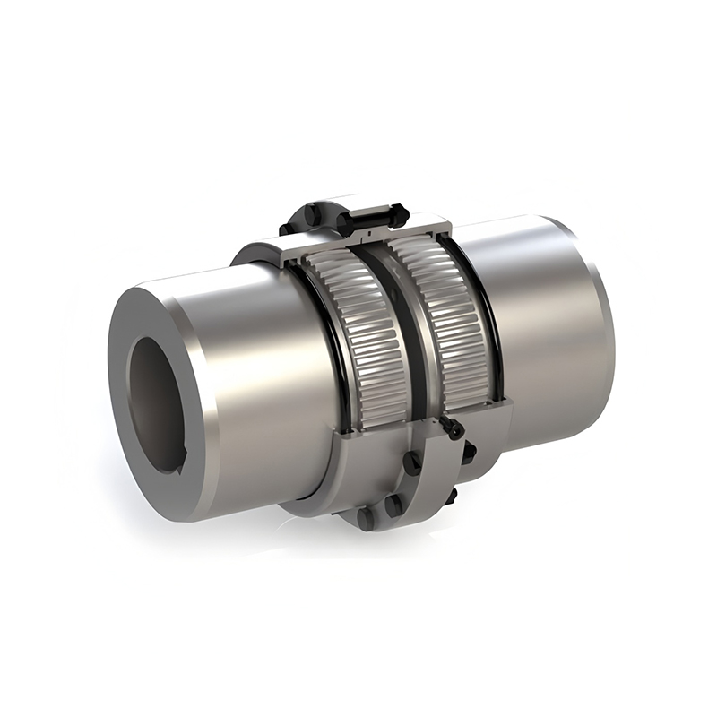
| Gear | Crowned gear teeth | High–Very High | Angular (up to 1.5°) | Steel mills, paper machines, heavy conveyors |
| Serpentine Spring (Grid) | Interlocking spring grid | High | Angular + Axial | Compressors, crushers, shock-load drives |
| Disc / Diaphragm | Thin metal disc pack | Medium–High | Angular + Axial | Servo drives, turbines, precision systems |
| Oldham | Sliding center disk | Low–Medium | Parallel (pure radial) | Encoders, lead screws, stepper motors |
Jaw (spider) couplings are the go-to solution for general industrial equipment. The elastomeric spider between the interlocking jaws absorbs shock, provides electrical isolation between shafts, and requires no lubrication. When the spider fails from overload—it will fail before the hubs—replacement is quick and inexpensive, which is exactly the behavior engineers design for. For pump-motor connections, encoder drives, and conveyor systems, jaw couplings offer a reliable, low-maintenance default choice. Explore servo motor coupling solutions including jaw and spider variants engineered for precision motion control.
Gear couplings use crowned external teeth meshing with internal sleeve teeth to handle very high torque at elevated speeds—applications where elastomeric elements would be destroyed by the loads involved. Steel mills, large paper machines, and heavy conveyor drives commonly rely on gear couplings. The trade-off is mandatory lubrication; insufficient grease is the leading cause of gear coupling failure in the field. For drum gear couplings for heavy-load transmission, crown tooth geometry distributes contact stress across a wider zone, extending service intervals under high-load cycling.
Serpentine spring couplings interlock two toothed hubs through a continuous spring grid seated in matching grooves. The spring progressively stiffens under increasing load—soft enough to absorb shock at startup, rigid enough to transmit full torque at running speed. This load-proportional behavior makes them particularly effective in compressor and crusher drives where sudden load spikes are routine. For broader flexible coupling solutions for industrial drives, tire and elastic pin designs cover applications where multi-directional misalignment compensation takes priority over torsional stiffness.
Specialized Coupling Types for Demanding Applications
Beyond the standard flexible families, several coupling categories address specific performance requirements that general-purpose designs cannot meet.
Cardan shafts (universal joint assemblies) transmit torque across large angular offsets—often 15° to 25°—that would be impossible for any other coupling type. A classic double-cardan arrangement uses two U-joints connected by a slip yoke, canceling the velocity fluctuation that a single joint produces at angle. Rolling mills, steel processing lines, and heavy vehicle drive systems rely on cardan shafts where the driving and driven equipment cannot be positioned on a common axis. Cardan shaft and universal joint assemblies cover both standard telescoping and fixed-length configurations for these high-angle drive requirements.
High-speed diaphragm couplings are the coupling of choice for turbomachinery, test bench drives, and high-RPM power generation equipment. A pack of thin stainless steel diaphragms flexes to accommodate misalignment while remaining torsionally stiff—transmitting torque with minimal angular windup, which matters enormously when precise phase relationships between shafts are required. Unlike gear couplings, they need no lubrication and introduce no backlash, making them suitable for operation above 10,000 RPM. Reviewing high-speed diaphragm coupling designs reveals how multi-diaphragm stack configurations balance axial flexibility with torsional rigidity across different speed and power classes.
DIN-standard couplings serve markets where dimensional interchangeability across manufacturers is contractually required, particularly in European process industries and OEM machinery built to German engineering specifications. Torsionally rigid variants (ZW/ZWN types) lock shafts together without angular play for positioning-critical drives; torsionally flexible variants (RUPEX, EUPEX series) add elastomeric elements for shock absorption while maintaining DIN dimensional compliance.
Constant-velocity (CV) joints solve a different problem: they transmit torque at a uniform output speed regardless of the angle between shafts. Unlike a standard U-joint, which accelerates and decelerates twice per revolution when running at angle, a CV joint maintains true constant velocity output. Industrial CV joints appear in rolling mill drive lines, test bench setups, and any high-precision application where velocity ripple from a conventional universal joint would introduce unacceptable measurement or process error.
How to Select the Right Shaft Coupling for Your Application
Coupling selection narrows quickly when approached systematically. Six engineering questions cover the majority of real-world decisions:
- What torque must it transmit? Start with the maximum continuous torque, then apply a service factor for the load type—typically 1.25–1.5 for smooth loads, 2.0–3.0 for shock or reversing loads. Size the coupling to the factored torque, not the nameplate motor rating.
- What is the operating speed? High-speed operation above 3,000–5,000 RPM typically demands dynamically balanced metallic couplings (diaphragm or disc). Elastomeric elements can degrade from centrifugal stress at elevated speeds and require explicit RPM rating verification.
- How much misalignment exists—and in which directions? Angular, parallel, and axial misalignment require different coupling geometries. Oldham couplings excel at pure parallel offset; cardan shafts handle large angular offsets; tire couplings manage all three simultaneously but at lower torque capacity.
- What are the environmental conditions? Temperature extremes, chemical exposure, wash-down requirements, and explosive atmosphere classifications all constrain material choices. Elastomeric spiders rated for standard temperatures (typically up to 80–100 °C) will soften and fail prematurely in higher-temperature environments; metallic couplings tolerate wider temperature ranges but may require corrosion protection in wet or chemical service.
- What space is available? Radial and axial envelope constraints frequently eliminate otherwise suitable coupling types before any other factor is considered. Beam couplings and bellows couplings serve compact precision applications where standard jaw or disc couplings would not fit.
- What are the maintenance requirements? Gear couplings require periodic re-greasing; elastomeric couplings need element inspection and eventual replacement; metallic disc and diaphragm couplings are wear-free but sensitive to installation-induced stress from over-torqued fasteners. Match the maintenance model to the facility's actual service capacity.
For reference, design equations covering torque capacity, shaft fit tolerances, and service factor methodology—including AGMA Standard 514-02 load classifications and ISO 1940 balance quality guidelines—are compiled in the shaft coupling design equations and standards reference at Engineers Edge, a useful complement to manufacturer selection tools when specifying couplings from first principles.
The most common selection mistake is treating coupling type as a secondary decision—something chosen after the motor, gearbox, and driven equipment are already committed. Coupling geometry affects shaft spacing, bearing loads, and alignment tolerances for the entire drivetrain. Engineering the coupling into the system from the beginning, rather than fitting one in at the end, consistently produces better outcomes in reliability and total maintenance cost.
