





 English
 русский
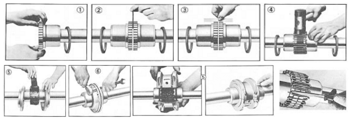
The performance of the coupling depends largely upon how you install and maintain.The Grid couplings are designed to be operating in either horizontal or vertical position without modification.
1.Mount Seals and Hubs
Clean all metal parts using nonflammable solvent and check hubs, shafts and keyways for burrs. Lightly coat seals with grease and place on shafts, before mounting hubs. Mount hubs on their respective shafts so the hub face is flush with the end of its shafts unless otherwise indicated. Tighten screws when furnished.
2.Gap and Angular Alignment
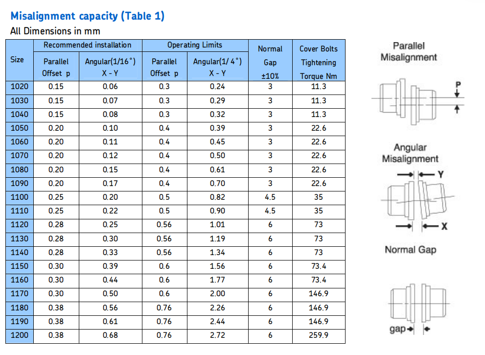
Using a spacer bar equal in thickness to the gap specified in Table 1. Insert bar as shown in fig to same depth at 90° intervals and measure clearance between bar and hub face with feelers. The difference in minimum and maximum measurements must be not exceed the angular limits specified in Table 1
3.Offset Alignment
Align so that a straight edge rests squarely (or within the limits specified in Table 2) on both hubs and also at 90° intervals. The clearance must not exceed the Parallel Offset installations limits specified in Table 1. Tighten all foundation bolts and repeat Steps 2 and3. Realign coupling if necessary.
4. Insert Grid
Pack gap and grooves with specified lubricant before inserting grid. Fix the Grid in the same direction; this will assure correct grid contact with non-rotating pin in cover halves.Spread the grid slightly to pass over the coupling teeth and seat with a soft mallet.
5. Pack with Grease and Assemble Covers
Pack the spaces between and around the grid with as much lubricant as possible and wipe off excess flush with top of grid. Position seals on hubs to line up with grooves in cover.Position gaskets on flange of lower cover half and assemble covers so that the match marks are on the same side. Push gaskets in until they stop against the seals and secure cover halves with fasteners, tighten to torque specified in Table. Make sure gaskets stay in position during tightening of fasteners.
 Previous