





 English
 русский
 中文简体
中文简体A petrochemical circulating pump train lost a gear coupling every nine months. The root cause was a motor outlet flange sitting 1.2 mm above the pump inlet, a number well within cold-alignment tolerances but destructive for lubricated gear teeth at 3,600 rpm. The maintenance team switched to a double-diaphragm coupling with a spacer, and the replacement interval stretched past four years. That outcome is typical: diaphragm couplings fail less often because they have no teeth to wear, no grease to lose, and no elastomer to age.
Content
How a Diaphragm Coupling Works
A diaphragm coupling transmits torque across a thin metal disc, or a stack of thin discs, bolted alternately to the driving and driven flanges. When rotation starts, the torque path passes through the diaphragm in shear and tension around the bolt circle. The disc deforms elastically to absorb angular and axial movement, which is what makes the coupling flexible.
A complete assembly usually contains a left hub, a diaphragm pack, a spacer shaft, a second diaphragm pack, and a right hub. The spacer shaft lets the coupling bridge a gap between two machine shafts, and it is also the element that makes double-flexing designs possible.
Two rules govern nearly every diaphragm coupling decision. First, a single diaphragm set handles angular misalignment only. If the machine has parallel shaft offset, you need two sets of diaphragms spaced apart, because that combination creates a floating center section that translates offset into angular deflection. Second, because torque flows through preloaded bolt joints, diaphragm couplings are inherently backlash-free.
Single Versus Double Diaphragm Designs
The distinction matters more than most datasheet comparisons admit. A single-diaphragm coupling is stiff in every direction except axial and angular. It suits close-coupled motors, encoders, and torque sensors where the shafts are aligned within fractions of a millimeter. A double-diaphragm unit is the right choice when you need to accept a measured offset and still transmit torque smoothly.
| Parameter | Single diaphragm | Double diaphragm |
|---|---|---|
| Angular misalignment | Up to about 1 degree per pack | Up to about 1 degree per pack |
| Parallel offset | Not recommended | Yes, proportional to spacer length |
| Axial travel | Limited | Moderate |
| Typical duty | Servo axes, encoders, test stands | Pumps, compressors, generator sets |
| Torsional stiffness | Very high | High |
Single diaphragm packs made of high-strength aluminum alloy keep inertia low, which is valuable for servo axes and positioning tables. This configuration is available with clamp hubs across a compact bore range.
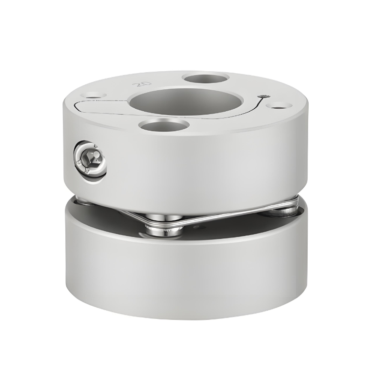 RSK-CPSM Aluminum Single Diaphragm Coupling with Clamp HubsThis coupling uses a high-strength aluminum alloy sleeve and a 304 stainless steel diaphragm. Its low inertia and high torque rigidity suit servo axes and positioning tables requiring precise rotation control.View Product →
When the drive train has a parallel offset that cannot be eliminated, an aluminum double-diaphragm coupling is a practical answer for compact CNC spindles and machine axes.
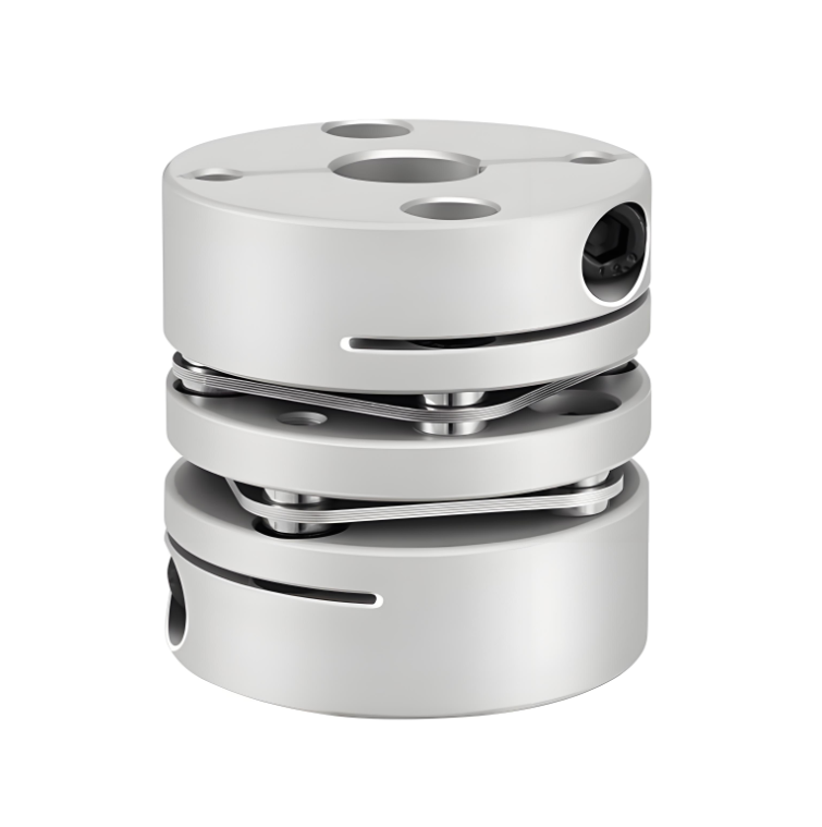 RSK-CPLF Aluminum Double Diaphragm Coupling for CNC SpindlesFeaturing a short clamp design with an aluminum alloy sleeve and stainless steel diaphragms, this coupling addresses parallel offset in compact CNC spindles and machine axes, offering precise control for servo and stepper motors.View Product →
Where Diaphragm Couplings Earn Their Keep
Diaphragm couplings are standard in rotating equipment where downtime is expensive and speeds are high. The most common duty is turbomachinery: steam and gas turbines, centrifugal compressors, and large process pumps. These machines run at thousands of revolutions per minute, grow several millimeters as they heat up, and cannot tolerate a coupling that needs attention between overhauls. A steel diaphragm coupling with two flex packs and a spacer covers all of those conditions without lubrication.
The application range is wider than turbines, though. High-speed test benches run diaphragm couplings between the drive motor and the torque flange, where zero backlash and a stable balance grade matter more than raw torque capacity. Marine auxiliary drives use them where seawater atmosphere would attack lubricated couplings. On the precision side, servo gearboxes, ball screws, and CNC spindles use small aluminum diaphragm couplings because they introduce no backlash and keep inertia low.
For test cell duty at speeds up to 10,000 rpm, a customized high-speed diaphragm coupling balances multiple diaphragm packs with tight manufacturing tolerances and a documented balance grade for sustained high-speed operation.
Selection Criteria and Common Specification Mistakes
Choose a diaphragm coupling by defining six parameters before looking at a catalog:
- Torque: use the peak or overload torque, not only the motor rated torque, and apply a safety factor of 1.5 to 2 for cyclic loads.
- Misalignment: measure angular and offset values at operating temperature and include thermal growth of the machine casings.
- Speed: confirm the coupling maximum RPM and balance grade against the fastest continuous speed the train will see.
- Axial travel: account for shaft expansion, and choose a double-flex design with spacer if travel exceeds a few tenths of a millimeter.
- Bore and mounting: decide between clamp hubs and keyed hubs; clamp hubs simplify installation and remove key backlash.
- Environment: temperature, humidity, and washdown chemicals decide the material family, typically aluminum or stainless steel.
Two specification mistakes recur. The first is undersizing for peak torque: a coupling that holds 1,000 N·m statically may not survive 500 N·m of cyclic torque at 6,000 rpm indefinitely, because the diaphragm fails in fatigue, not in static overload. The second is ignoring axial stiffness. In a close-coupled machine, an axially stiff coupling can push significant force into the equipment bearings when the shafts grow thermally, so the specified axial travel must be matched to the actual thermal growth.
How Diaphragm Couplings Compare With Gear and Elastomeric Designs
Diaphragm couplings usually end up competing against gear couplings and elastomeric couplings.
| Property | Diaphragm | Gear | Elastomeric |
|---|---|---|---|
| Lubrication | None | Grease required | None |
| Backlash | Zero | Grows with tooth wear | Low to moderate |
| Torsional stiffness | High | Highest | Low to moderate |
| Misalignment capacity | Moderate | High | High |
| Temperature range | -40 to +260 degrees Celsius | Broad | Limited by elastomer |
| Maintenance | Visual inspection | Re-lubricate, inspect teeth | Replace element |
Gear couplings deliver more torque per size and accept more misalignment, but they need grease, their backlash grows permanently as teeth wear, and they demand disciplined maintenance. Elastomeric couplings are inexpensive and forgiving, but they soften the drive train, lower natural frequencies, and wear out faster under continuous torque. A diaphragm coupling sits between the two: zero lubrication, zero backlash, high torsional stiffness, and moderate misalignment capacity with a predictable fatigue life. Engineers who want to review the broader performance logic behind this trade-off can read the summary of coupling advantages on the company site.
Maintenance and Expected Service Life
Diaphragm couplings are often labeled maintenance-free because there are no lubricated parts. In practice that means maintenance is periodic and visual rather than constant.
- Inspect the diaphragm packs for cracks, fretting, or corrosion, especially around the bolt holes.
- Check bolt torques after the first weeks of operation and after any coupling overhaul.
- Verify alignment, balance marks, and fastener condition when the machine is opened for maintenance.
Service life is limited by metal fatigue, not sliding wear. Large industrial diaphragm couplings in clean service commonly exceed ten years before a diaphragm pack needs replacement. When fatigue cracks do appear, the diaphragm pack is replaced as a module and the hubs and spacer can continue in service, which keeps lifecycle cost low.
The reliable way to specify a diaphragm coupling is not to pick it by bore size alone. Define the torque envelope, the real misalignment between flanges at operating temperature, the speed and balance class, and the axial travel the equipment will generate. Once those numbers are written down, the design choice becomes straightforward. Jiangsu Rokang manufactures aluminum and steel single and double diaphragm couplings plus high-speed units for rotating test equipment, and the complete range is organized by duty on the corporate site.
 Previous