





 English
 русский
 中文简体
中文简体A plant engineer once asked why his pump coupling kept damaging disc packs even though the shafts were aligned to within 0.05 mm. The coupling had been selected on torque alone. Nobody considered the axial thrust produced when the disc pack was deflected by the pump's thermal growth, and the cyclic load was slowly fretting the laminations at the bolt circle. Disc coupling design is the discipline of balancing torsional stiffness, misalignment capacity, and restoring force against the real operating envelope. Get the balance right and the coupling becomes a fit-and-forget component; get it wrong and it becomes a recurring source of downtime.
Content
- 1 What a Disc Coupling Design Must Deliver
- 2 Disc Pack Geometry: Straight-Side vs Scalloped
- 3 Material and Lamination Thickness
- 4 Bolted Joints and Pre-Stretch
- 5 Torsional Stiffness vs Restoring Force: The Trade-Off That Protects Machinery
- 6 Disc Coupling vs Gear Coupling: Design Priorities in Comparison
- 7 High-Speed and Custom Disc Coupling Design
- 8 A Practical Disc Coupling Design Review Checklist
What a Disc Coupling Design Must Deliver
A disc coupling transmits torque through thin stainless steel laminations arranged in packs. The design job starts with three measurable requirements:
- Transmit the rated torque with high torsional stiffness and zero backlash.
- Accommodate parallel misalignment, angular misalignment, and combined misalignment within defined limits.
- Absorb axial movement (end float) while keeping the reaction forces on driver and driven bearings within acceptable values.
The first two requirements are usually obvious. The third is the one that separates good designs from problematic ones. Every disc pack has a finite axial and bending stiffness, and when the coupling is deflected, it generates restoring forces. Those forces travel directly into the connected machine's bearings and seals. A design that maximizes torque capacity by stacking more laminations will also become stiffer in bending, and the bearing loads rise accordingly.
| Design input | Why it matters |
|---|---|
| Rated and peak torque | Determines disc pack size, number of laminations, and bolt diameter. |
| Operating speed | Sets balance quality grade and, for high speeds, critical speed margins. |
| Parallel misalignment | Drives disc pack diameter and scalloped profile selection. |
| Angular misalignment | Limits the number and thickness of laminations. |
| Axial thermal movement | Determines axial stiffness requirement and spacer length. |
| Allowable bearing reaction | Constrains restoring force and therefore total stack thickness. |
Disc Pack Geometry: Straight-Side vs Scalloped
The shape of each lamination controls how stress spreads through the pack under load. Two geometries dominate industrial practice.
Straight-sided disc packs have a solid contour between the inner and outer bolt circles. They offer the highest torque density for a given envelope and are relatively inexpensive to produce. Their downside is that stress concentrates around the bolt holes, which limits the amount of angular deflection the pack can absorb without fatigue damage.
Scalloped or profiled disc packs remove material between adjacent bolts, creating a curved contour. The profile distributes stress across a wider area and allows greater angular misalignment at the same cyclic stress level. The trade-off is a slightly lower torque capacity for the same diameter, which is why scalloped packs dominate in pump, compressor, and other rotating equipment applications where misalignment capability matters more than absolute compactness.
For general industrial drive trains, a scalloped-pattern disc coupling with aluminum alloy hubs and clamp-type fixing provides a practical balance of misalignment capacity, torsional rigidity, and compactness.
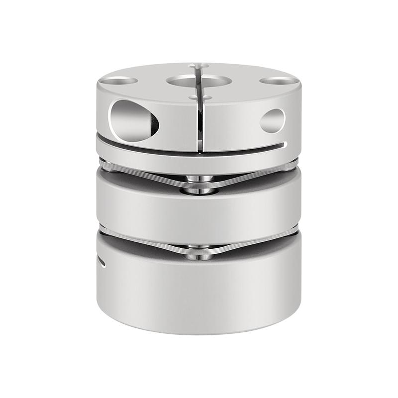 RSK-CPL Aluminum Alloy Diaphragm Coupling with 304 Stainless Steel DiscThis clamp-type coupling uses an aluminum alloy hub and a 304 stainless steel diaphragm, offering low inertia and high torsional rigidity for precise servo and stepper motor applications.View Product →
Material and Lamination Thickness
Disc material selection is driven by corrosion resistance, temperature, and fatigue endurance. Precipitation-hardened stainless steels are the default choice because they combine high yield strength with good corrosion resistance and stable behavior at temperatures up to about 300°C. For salt-laden or chemically aggressive environments, more highly alloyed stainless grades reduce the risk of pitting and stress-corrosion cracking, while a blackened 45-steel pack with corrosion-resistant finish is a practical middle-ground for drier industrial settings.
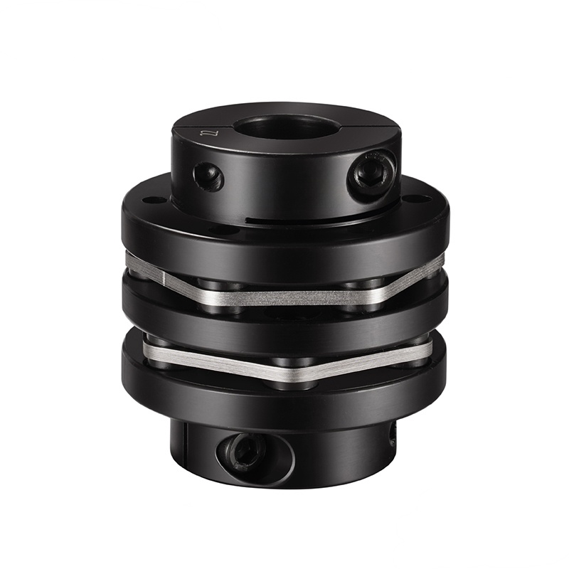 RSK-CPNLT 45# Steel Stepped Double Diaphragm Coupling with Blackening FinishFeaturing a keyed 45# steel hub and a 304 stainless steel diaphragm, this clamp coupling delivers large torque transmission and corrosion resistance for demanding industrial drive trains.View Product →
Lamination thickness is a direct design lever. Thin laminates produce a lower restoring force for a given deflection, which protects bearings, but they provide less axial load capacity per pack. Thicker laminates carry more torque and axial load but make the pack stiffer in both bending and axial directions. Most designs use a stack of identical thin laminates rather than one thick plate precisely because the laminated stack decouples load capacity from flexibility: adding laminations raises torque capacity without increasing the bending stiffness of any single element.
Bolted Joints and Pre-Stretch
Torque is transferred between the inner and outer bolt circles through the clamping force of the bolts. In a correctly designed joint, friction between the laminations carries the load; the bolts themselves are not working in shear. This is why tightening procedure and preload control are part of the design, not an afterthought.
Pre-stretch refers to the deliberate tensioning of the disc pack bolts to a specified preload. If the clamping force is too low, the laminations will slip against each other at every load reversal, producing fretting wear at the bolt holes. Fretting is the most common disc coupling failure mode in the field, and it is almost always traceable to insufficient or inconsistent preload, or to hardened washers missing under the bolt heads.
A well-designed bolted joint uses controlled bolt tension, hardened washers or collars, and a surface finish that resists micro-slip. When a coupling is assembled without these details, the design intent of the disc pack is compromised from day one.
Torsional Stiffness vs Restoring Force: The Trade-Off That Protects Machinery
The defining characteristic of a disc coupling design is the combination of high torsional stiffness in the direction of rotation with low bending stiffness in the plane of misalignment. This allows torque transmission without windup while still accepting shaft displacement.
Restoring force is the lateral or axial force generated when the disc packs are deflected from their neutral position. Lower restoring forces increase bearing and seal life because the machine is not carrying a permanent side load. Designers therefore aim for the thinnest practical laminations and the smallest pack diameter that still satisfies torque and speed requirements.
While every bearing has its own allowable radial load, a useful benchmark is to keep the coupling's maximum restoring force below the bearing's continuous rating by a wide margin. Reaching that limit is surprisingly easy when designers add laminations to chase torque capacity without revisiting the stiffness calculation.
Disc Coupling vs Gear Coupling: Design Priorities in Comparison
Disc couplings and gear couplings take different approaches to misalignment, and the design priorities are correspondingly different. Gear couplings transmit torque through crowned gear teeth that allow relative sliding between the hub and sleeve; they handle large torques in compact envelopes and tolerate substantial misalignment, but they require lubrication, and fretting at the tooth flanks remains a long-term maintenance concern. Disc couplings use flexible metallic elements in bending and carry no sliding parts, so they run without lubrication and produce much lower restoring forces.
| Characteristic | Disc coupling | Gear coupling |
|---|---|---|
| Lubrication | None required | Grease or oil required |
| Restoring force | Low to moderate | Moderate to high |
| Misalignment capability | Good angular, limited parallel | Large angular and parallel |
| Torque density | Moderate | High |
| Backlash | Zero | Minimal but present |
Where high torque density and large misalignment are the dominant requirements, gear couplings remain the conventional choice, and the operating principles of drum gear couplings explain why they continue to dominate heavy mill drives. But where precision, clean operation, and low bearing load matter more than absolute torque density, the disc coupling design is the stronger candidate.
High-Speed and Custom Disc Coupling Design
High-speed service introduces a different set of constraints. At operating speeds above roughly 3,600 rpm, the coupling's unbalance directly excites lateral rotor modes, and the designer must verify that the coupling's running speed does not coincide with a critical speed of the rotor system. Balance quality grades are specified in accordance with ISO 1940-1, and for couplings operating at 10,000 rpm or more, a multi-plane balance is normally required.
Windage losses and aerodynamic drag on the outer surface also grow with speed, which is why high-speed disc couplings are machined with smooth profiles and no protruding fasteners. Axial positioning of the spacer, diaphragm thickness, and the flexural stiffness between the two packs all affect the system's lateral natural frequencies.
Custom designs are common in this range. Test stand couplings, turbomachinery, and high-speed blower drives frequently require non-standard hub bores, stepped shafts, or brake discs integrated into the coupling body. A manufacturer that controls the full design and machining process can adapt the disc pack geometry and hub configuration without compromising the balance specification.
A Practical Disc Coupling Design Review Checklist
Before a disc coupling design is finalized, the following points should be checked against the actual machine data rather than assumed from a generic duty classification.
- Torque: confirm both continuous torque and worst-case peak torque, including starting and jam conditions.
- Misalignment: measure the real installed misalignment, not the catalogue maximum; the design margin disappears quickly when both parallel and angular misalignment act at the same time.
- Axial movement: include thermal growth and any axial float of the driven machine; the axial stiffness of the disc pack converts this movement into thrust load.
- Restoring force: compare the calculated restoring force against the bearing manufacturer's allowable radial load.
- Speed: verify the balance quality grade and check that no lateral critical speed falls within the operating range.
- Environment: assess temperature range, humidity, chemical exposure, and whether an all-metal design is required for ATEX or similar duty.
- Installation: confirm that bolts, washers, and tightening tools are specified, since preload is decisive for fretting resistance.
Disc coupling design is not simply a torque calculation. The best designs are the ones where the restoring force, the misalignment capacity, and the fatigue life of the laminations have all been calculated against real running conditions, because the coupling that never fails is the one that was designed for the system, not for the catalogue.
 Previous