





 English
 русский
 中文简体
A 15 kW centrifugal pump at a chemical plant was eating jaw-type flexible motor couplings every eight months. The coupling was not the problem. Measurement showed the motor and pump shafts sitting 0.9 mm apart in parallel offset and 0.6 degrees out of angular alignment, roughly three times what the spider insert could absorb. The replacement failed the same way. A flexible motor coupling is a torque-transmitting part with a fixed, finite misalignment allowance. Treating it as a cure for poor alignment is the most reliable way to keep buying the same part twice a year.
Content
- 1 What a Flexible Motor Coupling Does, and What It Cannot Do
- 2 The Flexible Motor Coupling Types You Will Actually Specify
- 3 Selection Sequence: Torque, Misalignment, Speed, Fit
- 4 Installation Details That Decide Coupling Life
- 5 Failure Patterns and What They Tell You
- 6 Matching the Coupling to the Driven Machine
- 7 What to Send a Manufacturer for an Accurate Quote
What a Flexible Motor Coupling Does, and What It Cannot Do
A flexible motor coupling joins the motor shaft to the input shaft of a pump, gearbox, compressor, fan or machine tool. It performs three jobs at once: it transmits torque, it absorbs the small shaft offsets that no real installation eliminates, and it reduces the vibration and shock that would otherwise reach motor bearings and gear teeth. The word flexible describes the working element, whether that is an elastomer insert, a metal bellows, a stainless disc pack, a helical beam section or a spring grid. It does not describe an unlimited ability to swallow misalignment.
What the part will not do matters just as much. It cannot pull two badly aligned shafts into line, absorb the thermal growth of a long shaft train, compensate for a soft foot, or act as a spacer between machines that should have been positioned correctly in the first place. Every flexible design also carries a cost. Elastomeric types damp vibration well but have temperature limits and a finite service life; metallic types hold zero backlash and tolerate heat but pass vibration through and can fatigue. The payoff, which comes down to lower bearing loads, less noise and longer machine life, is summarised in this note on the advantages of a flexible coupling.
The Flexible Motor Coupling Types You Will Actually Specify
Motor-driven machinery is served by eight coupling families in practice. The table below lists the misalignment each one handles in service and the drives where it earns its place. Treat the figures as planning values rather than limits.
| Coupling type | Flexing element | Typical parallel / angular allowance | Where it fits |
|---|---|---|---|
| Jaw (spider) | Nitrile or polyurethane insert | 0.3 to 0.5 mm / 1 degree | Pumps, fans and conveyors up to about 45 kW; insert is a service item |
| Beam (helical) | Machined aluminium or stainless beam | 0.2 to 0.5 mm / 2 to 5 degrees | Encoder, small servo and instrument drives |
| Bellows | Welded metal bellows | 0.15 to 0.3 mm / 1 to 2 degrees | Servo axes, high-speed spindles, zero-backlash drives |
| Diaphragm (disc) | Stainless steel disc pack | 0.2 to 0.5 mm / 0.5 to 1.5 degrees | Test benches, compressors, hot or high-speed drives |
| Oldham (cross slider) | Sliding disc between two hubs | 1 to 3 mm / under 1 degree | Large parallel offset at low speed, constant velocity |
| Elastic sleeve pin | Pins fitted with rubber or plastic sleeves | 0.5 to 1 mm / 0.5 to 1 degree | General industrial drives from 15 to 200 kW |
| Tyre | Rubber tyre bolted to both flanges | 1 to 4 mm / 4 to 6 degrees | Shock and vibration-heavy drives, dredgers, crushers |
| Serpentine spring | Wound spring grid in a flanged housing | 0.3 to 1 mm / 0.5 to 1.5 degrees | Reversing and shock loads, cranes, rolling mills |
Two rules matter more than the numbers. Keep working misalignment to about one third of the rated allowance, because a coupling already running at its limit has no reserve for thermal growth or foundation settling. And match the element material to the environment: nitrile inserts are comfortable from about -40 °C to 100 °C, polyurethane slightly less at the top of that range, while a bellows or diaphragm pack is limited by fatigue life rather than by temperature.
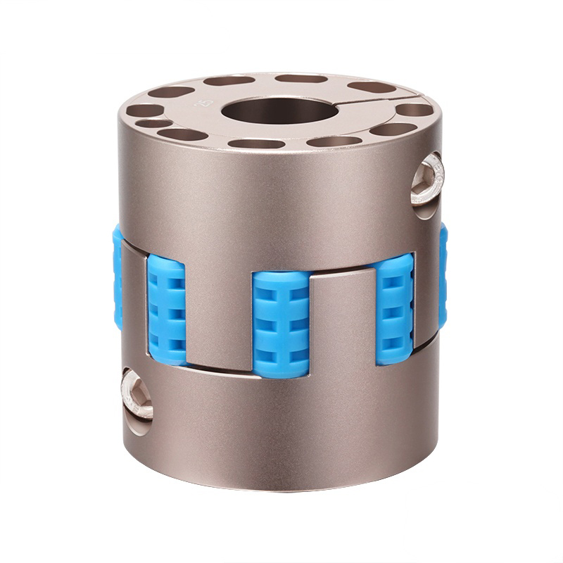 RSK-CPFJC High-Rigidity Aluminum Jaw Spider CouplingWhen sizing a motor-driven coupling, this zero-backlash aluminum jaw/spider unit damps vibration and compensates offset under calculated torque and misalignment.View Product →
Selection Sequence: Torque, Misalignment, Speed, Fit
Torque and service factor
Start from the driven machine, not the motor. Required torque is T = 9550 x P / n, with P in kW and n in rpm, so a 22 kW motor at 1470 rpm needs about 143 Nm. Multiply by a duty service factor: roughly 1.5 for smooth fans and centrifugal pumps, 2.0 for conveyors, mixers and reciprocating compressors, and 2.5 or more for crushers, roller presses and reversing drives. Then confirm peak torque. A direct-on-line motor can deliver two to three times rated torque at start-up, and the coupling's peak rating, not its continuous rating, governs that moment.
Misalignment budget
Measure the offset after the machines are grouted and bolted, not from the drawing. Add thermal growth between cold and hot states. Then choose a size whose rated parallel, angular and axial allowances are at least three times what you expect to see. Axial allowance is the one most often forgotten: a bellows coupling on a shaft train that grows 1 mm when hot will fail in thrust long before it fails in torsion.
Speed, balance and backlash
Above roughly 3000 rpm balance becomes a selection criterion rather than a footnote, and a coupling that behaves at 1500 rpm may vibrate at 6000 rpm if the assembly is not balanced as a unit. On servo and positioning axes, backlash and torsional stiffness outrank torque capacity, which is why clamp-type hubs and zero-backlash elements replace set screws and elastomer inserts in those positions.
Installation Details That Decide Coupling Life
- Align with a dial indicator or laser system in two planes, then recheck after the first day of running.
- Set the hubs so the flexing element sits at its designed gap, and never use the coupling to close a shaft gap.
- Respect the bore fit. An H7 bore on an h6 shaft with the correct key slides on without force; a loose bore frets within weeks, and a hammered-on hub damages bearings.
- Tighten clamp screws and pin bolts with a calibrated wrench, in the sequence shown on the drawing.
- Keep elastomer elements away from oil, ozone and direct sunlight in storage, and inspect them at planned shutdowns rather than waiting for a breakdown.
Failure Patterns and What They Tell You
- A spider insert worn into a crescent shape points to angular misalignment; even wear across all lobes points to overload.
- A metal bellows cracked next to a flange usually means repeated axial or angular overtravel, not a material defect.
- Flattened or melted pin sleeves indicate ambient or radiant heat above the elastomer limit.
- A fretted hub bore and keyway show a loose fit combined with torque reversal.
- A coupling running hot at moderate load is often over-compressed axially during installation.
Matching the Coupling to the Driven Machine
On a centrifugal pump, fan or screw conveyor driven by a standard induction motor of 7.5 to 45 kW, a jaw-type or elastic sleeve pin coupling is usually the sensible choice. Both tolerate parallel and angular offset, damp the torsional ripple of the motor, and can be re-elemented on site in under an hour without moving either machine.
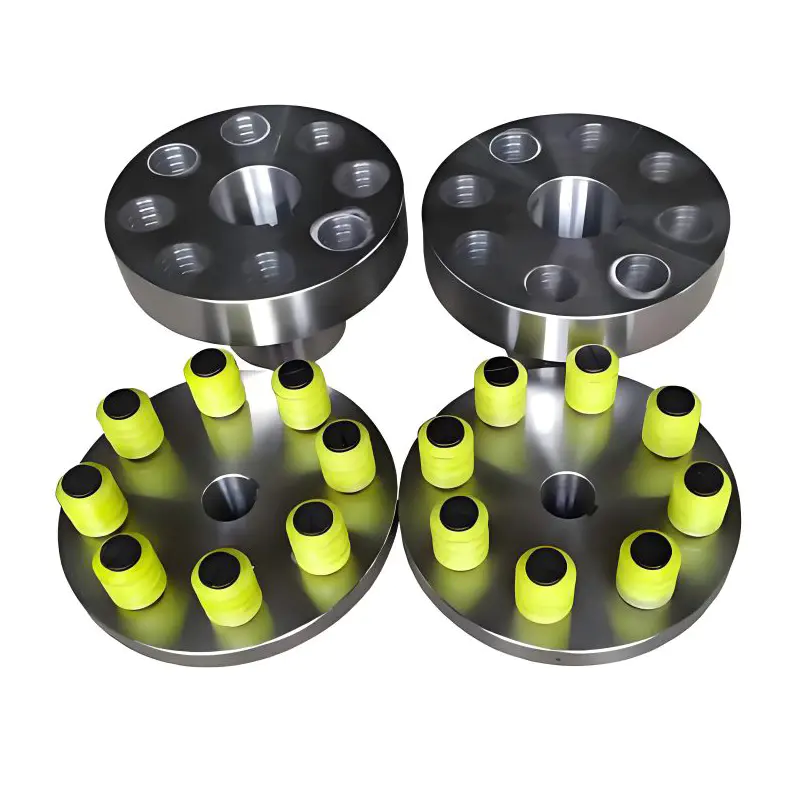 RSK-LT Elastic Sleeve Pin CouplingFor standard induction motor drives on fans, pumps or conveyors, this low-cost elastic pin coupling tolerates offset and simplifies on-site maintenance.View Product →
Servo and positioning axes are a different problem. Here backlash matters more than raw torque, so a metal bellows or beam coupling with clamp hubs keeps the connection rigid in torsion while still allowing a small offset. Because the servo coupling range includes beam, bellows, diaphragm, jaw and Oldham versions, a single mounting style can be kept across a whole machine.
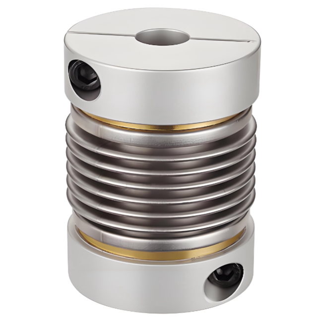 RSK-CPRC Aluminum Alloy Bellows Servo CouplingFor servo and stepper positioning axes where backlash matters, this clamp-type stainless bellows coupling compensates small offsets without losing torsional rigidity.View Product →
High-speed test benches, turbo compressors and machine tool spindles run past the balance and fatigue limits of elastomers, which is where a diaphragm coupling rated for 10000 rpm takes over. At the heavy end, roller presses, cranes, rolling mills and marine shafting call for drum gear or serpentine spring couplings, sometimes with a brake wheel, an intermediate shaft or a split hub, and often as a customised rather than catalogue assembly.
What to Send a Manufacturer for an Accurate Quote
A coupling quotation is only as good as the data behind it. Supply the following before asking for a price:
- Motor power, speed and starting method
- Shaft diameters, keyway dimensions and fit class on both sides
- Measured or expected parallel, angular and axial misalignment
- Duty cycle, shock level and whether the drive reverses
- Ambient temperature, moisture, dust and chemicals
- Operating speed and, above 3000 rpm, the required balance grade
- Whether a brake wheel, brake disc, intermediate shaft or split hub is needed
With that list, a supplier can pick a standard size, recommend the element material and confirm whether a modified bore, keyway or balanced assembly is required. That level of customisation is routine in industrial coupling manufacturing, and it is normally cheaper than specifying an oversized standard unit to cover an unknown.
The coupling is the cheapest component in most drive trains, and it fails most often for reasons that have nothing to do with the coupling itself. Fix the alignment, size for peak torque, keep a third of the misalignment allowance in reserve, and a flexible motor coupling will outlast the bearings on either side of it.