





 English
 русский
When a motor shaft coupling fails three months after installation, the usual suspect is not material quality but a mismatch between the coupling type and the real operating conditions. The shaft bores fit, the torque rating looked acceptable on paper, and yet the elastomer tore or the gear teeth wore out. In most plants, the root cause is one of three things: underestimated misalignment, ignored dynamic load, or the wrong coupling family for the application. Choosing a motor shaft coupling is a design decision, not a catalogue exercise. A correctly selected unit transmits torque reliably, absorbs unavoidable misalignment, and protects both the motor and the driven machine from destructive forces.
Content
What a motor shaft coupling actually does
A motor shaft coupling is a mechanical component that connects the output shaft of an electric motor, diesel engine, or other prime mover to the input shaft of a pump, gearbox, conveyor, compressor, or similar machine. Its primary job is to transmit torque while keeping the driver and driven shafts rotating in sync.
That simple description hides three secondary functions that usually decide whether a coupling survives in service. First, it compensates for shaft misalignment, whether parallel, angular, or axial. Second, it dampens vibration and absorbs shock loads before they reach motor bearings. Third, some designs act as a mechanical fuse, protecting expensive equipment when torque spikes exceed safe limits. A coupling that only transmits torque is doing less than half its job.
The consequences are practical. A coupling sized purely on nominal motor power, with no margin for cyclic loads, will fail early in a crusher or rolling mill. A rigid coupling installed where thermal expansion moves the shaft axially will generate high reaction forces. Understanding what a coupling must do on a specific machine is the starting point for every reliable drive train.
Rigid or flexible: the first decision
The first decision is whether the application needs a rigid or flexible coupling. Rigid couplings lock two shaft ends into a single solid unit. They are used when shafts are already held in precise alignment, typically in gearboxes and compact machine frames where the housing controls shaft position. They offer zero backlash and maximum torsional stiffness but tolerate no misalignment.
Flexible couplings accommodate misalignment and absorb dynamic loads. They dominate industrial motor drives because real installations rarely maintain perfect alignment. Motors settle on their foundations, thermal expansion shifts shafts, and process loads deflect frames. A flexible coupling absorbs these deviations while still transmitting the required torque.
The practical rule is: use a rigid coupling only when the machine design guarantees alignment, and use a flexible coupling for every motor-to-machine connection where alignment changes over time. Most pump, fan, compressor, and conveyor drives fall into the second group.
Main types of motor shaft couplings
Gear and drum gear couplings
Gear couplings transmit very high torque in a compact envelope. They use crowned external teeth on one hub engaging internal teeth on a sleeve, allowing moderate angular and axial misalignment. Drum gear couplings, with barrel-shaped teeth, increase the contact area and load capacity compared with straight-tooth designs.
For heavy industrial drives, drum gear couplings are the standard choice when space is limited and torque is high. The RSKGICL wide-type drum gear coupling is a representative design, with high load capacity for mills, kilns, and heavy conveyors. Manufacturers also supply intermediate-shaft versions for long distances and brake-wheel or brake-disc variants for crane and hoist duty. The trade-off is that gear couplings require lubrication and periodic inspection in dirty environments. A more detailed discussion of tooth geometry and application limits is available in the technical guide to drum gear couplings for heavy industrial drive systems.
 RSK-GICL Drum Gear Coupling Wide Type High load capacity and torque transmissionJiangsu Rokang Heavy Industry Technology Co., Ltd is RSK-GICL Drum Gear Coupling Wide Type High load capacity and torque transmission Sup...View Product →
Diaphragm and high-speed couplings
Diaphragm couplings transmit torque through a thin metal disc pack that flexes to accommodate misalignment. They are torsionally stiff, backlash-free, and maintenance-free, which makes them the default choice for high-speed rotating equipment such as turbines, compressors, and test stands.
The critical selection parameter is speed. A standard coupling may be unsuitable for continuous operation above a few thousand rpm, while a purpose-built high-speed coupling is balanced and designed for its service speed. For example, a customized high-speed diaphragm coupling rated up to 10,000 rpm can handle turbine-driven or test-bench applications where a standard design would vibrate excessively. The metal disc pack removes the wear and temperature limits of elastomer couplings, at the cost of slightly lower misalignment capacity.
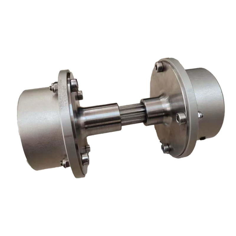 RSK customized high speed diaphragm coupling upto 10000rpm Suppliers, Company -Jiangsu Rokang Heavy Industry Technology Co., Ltd is RSK customized high speed diaphragm coupling upto 10000rpm Suppliers and Wholesale ...View Product →
Universal joints and cardan shafts
When the driver and driven shafts are not in line, or when the angle changes during operation, a universal joint or cardan shaft is the practical solution. Cardan shafts use cross-bearing universal joints at each end and often a telescopic middle section, so they transmit torque through angles that flexible couplings cannot handle.
Precision universal shafts with controlled fits are used in test benches, rolling mills, and vehicle drivelines where both angle and torque are significant. A double-type precision universal shaft combines two joints to maintain near-constant velocity over a range of angles, which matters for synchronized drives and multi-axle equipment. The trade-off is lower torsional stiffness than a one-piece shaft and the need for periodic lubrication of the cross bearings.
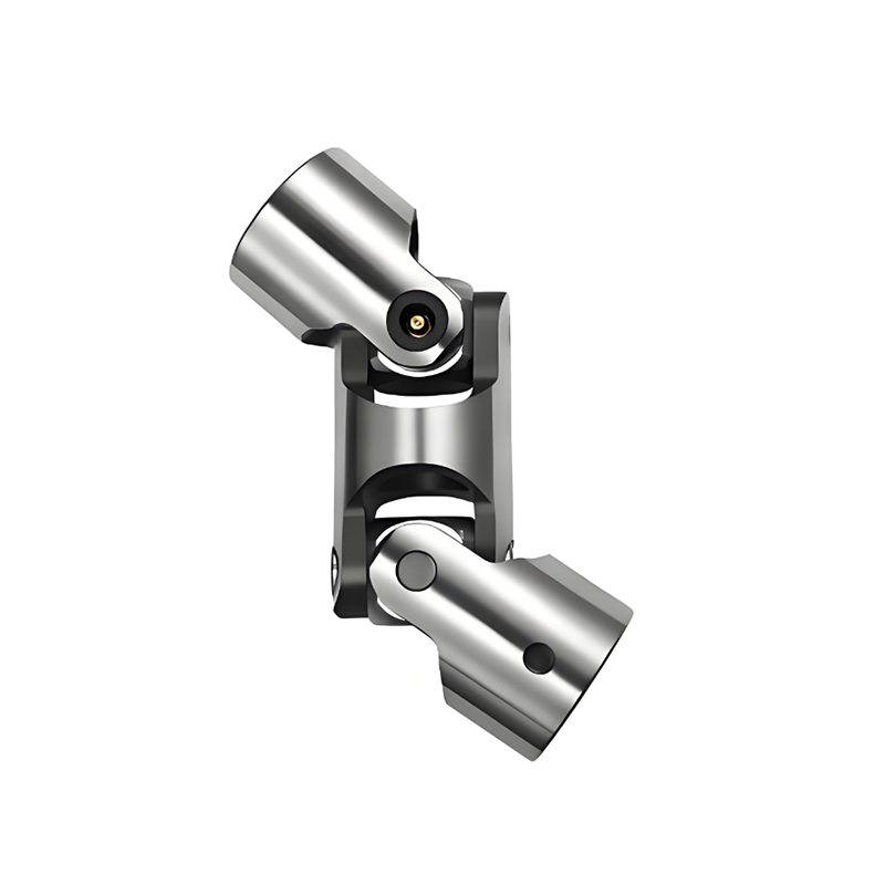 RSK-WS Precision Universal shaft Double type Large-Angle Torque Transmission SupJiangsu Rokang Heavy Industry Technology Co., Ltd is RSK-WS Precision Universal shaft Double type Large-Angle Torque Transmission Supplie...View Product →
Jaw, beam, bellows, and Oldham couplings
For lower-torque servo and general-purpose drives, lighter coupling families dominate. Jaw or spider couplings use an elastomer insert between two metal hubs to dampen vibration and accept misalignment at low cost. Beam couplings cut helical slots into a single piece of metal, producing a compact, backlash-free flex element. Bellows couplings provide high torsional rigidity and precise motion transfer for encoders and servo motors. Oldham couplings handle parallel misalignment with a floating center disc.
These types typically cover shaft sizes from a few millimeters to roughly 60 mm and torques up to a few hundred newton-meters, so they are found in machine tools, packaging equipment, and automation lines rather than heavy process plants.
Selection criteria that prevent premature failure
Selecting a motor shaft coupling requires the operating conditions, not just the motor nameplate. The table below summarizes the parameters that should be defined before purchase.
| Criterion | What to define | Typical guidance |
|---|---|---|
| Torque capacity | Continuous, starting, and peak torque with a service factor | 1.5 to 3 times nominal motor torque for most industrial drives |
| Speed | Maximum continuous speed and balancing grade required | Standard types to 3,600 rpm; high-speed types to 10,000 rpm and above |
| Misalignment | Parallel, angular, and axial allowance needed at installation and during operation | 0.1 to 2 mm parallel; 0.5 to 3 degrees angular, depending on coupling family |
| Shaft mounting | Bore diameters, keyway standard, or clamping hub design | Metric or inch bores; keyed or keyless hubs |
| Environment | Temperature, dust, chemicals, washdown exposure | -40 to +150 degrees Celsius for steel couplings; elastomer limits are lower |
| Maintenance | Lubrication interval and inspection effort accepted | Gear couplings need lubricant; diaphragm, beam, and Oldham types are maintenance-free |
These parameters interact, so they must be defined together. A coupling that is acceptable at 500 N·m and 1,500 rpm may fail at 4,000 rpm because centrifugal effects change the contact pattern. A high-torque gear coupling selected with too little misalignment allowance will develop edge loading on the teeth. Standardized rating procedures, such as those in the DIN coupling family, provide a useful framework; a practical overview of DIN coupling types, standards, and selection can help when specifying motor drives.
Supplier experience also matters. A manufacturer that produces the coupling family in volume, rather than reselling generic parts, can advise on realistic service factors and custom bore configurations, which prevents most early failures.
Where motor shaft couplings are used
Motor shaft couplings appear in every industry that rotates a machine with a motor or engine. The most common applications are:
- Steel and metal rolling: drum gear couplings and cardan shafts transmit high torques to rolling stands.
- Cranes and hoists: couplings with brake wheels combine power transmission with braking duty.
- Pumps and compressors: diaphragm or gear couplings connect motors to high-speed process machinery.
- Mining and bulk handling: flexible couplings absorb shock loads from crushers and conveyors.
- Marine propulsion: high-elasticity couplings reduce torsional vibration in ship shaft lines.
- Test and measurement: precision couplings with zero backlash ensure accurate torque readings.
Within these sectors, the coupling choice is driven by the same parameters discussed above. A steel mill gear coupling and a test-bench diaphragm coupling share the same engineering logic but use different materials, balancing, and lubrication schemes.
Installation practices that extend coupling life
Even a correctly specified coupling fails early if installation is wrong. Three practices prevent most problems. First, check the actual shaft bores before assembly. A coupling intended for a 55 mm shaft must not be forced onto a 56 mm shaft; the interference creates stress concentrations and makes removal difficult. Second, align the shafts to the values stated in the coupling data sheet, not to a visual estimate. For flexible couplings, alignment within the rated tolerance preserves the service life; for rigid couplings, alignment must be near perfect. Third, tighten the hub bolts to the specified torque in the correct sequence, then re-check after the first 100 operating hours, because bolted joints settle as the machine warms up and loads stabilize.
The engineering rationale behind these practices is covered in the discussion of the advantages of couplings in power transmission systems.
Sourcing from a manufacturer
The final consideration is where to buy. Standard catalogue couplings are widely available, but industrial drives often need custom bore sizes, special materials, or brake-wheel combinations. A factory-direct manufacturer can machine bores to supplied shaft drawings, balance high-speed units, and document the material and heat treatment used.
Jiangsu Rokang Heavy Industry Technology Co., Ltd. is a coupling and drive-shaft manufacturer with a product line covering constant-velocity joints, cardan shafts, drum gear couplings, diaphragm couplings, and locking assemblies. Its team works through design, machining, heat treatment, welding, and dynamic testing, which matters when a plant needs a traceable, repeatable product rather than a one-off import. For plants replacing worn couplings on existing machinery, confirming the original duty and measuring the actual envelope is the fastest route to a correct replacement.
The reliable motor shaft coupling decision follows five steps: define the duty, choose the coupling family, size it with a realistic service factor, verify the shaft and space envelope, and buy from a manufacturer that can support the application. Doing that work before installation is far cheaper than repeating it after failure.
 Previous