





 English
 русский
A 132 kW conveyor drive on a mining site went through three couplings in one operating season. Each replacement was the same catalogue size, and each one failed at the hub teeth. The fault was not material quality; it was a sizing method that looked only at shaft diameter and motor power. The duty cycle included frequent starts under a loaded belt, and nobody had measured the angular misalignment created by the settling foundation. That lesson applies across heavy industry: sizing shaft couplings for heavy equipment is an engineering calculation, not a catalogue lookup.
Content
The Sizing Logic That Prevents Field Failures
Work in the right order and most coupling failures disappear. Calculate the application torque, apply a service factor that reflects the driven machine and its duty, identify peak and shock conditions, measure the misalignment that the equipment actually produces, and only then select a coupling size that satisfies every constraint at the same time. A coupling that is perfectly rated for nominal torque can still fail quickly when it runs with continuous angular misalignment or when the starting torque reaches three times the running torque.
Design torque is the anchor of the whole calculation: Td = Tn x SF. Tn is the nominal torque transmitted under steady operation, and SF is the service factor. For heavy equipment, SF rarely sits below 1.5 and often reaches 2.5 to 3.0 for crushers and reversing mills. Two drives with the same motor torque can require different coupling sizes. A centrifugal pump running steadily at 1480 rpm typically uses a service factor of 1.25, while a crusher with the same motor needs 2.5 or higher because of shock loading. The table below lists service factors commonly used for electric motor drives.
| Driven machine | Service factor |
|---|---|
| Belt conveyor | 1.5-2.0 |
| Crusher | 2.0-2.5 |
| Centrifugal pump | 1.25-1.5 |
| Rolling mill | 2.5-3.0 |
| Crane travel drive | 1.5-2.0 |
The Three Numbers That Decide Coupling Size
Every shaft coupling selection comes down to three numbers: torque, bore, and misalignment. Speed and environment matter too, but these three decide the frame size.
Nominal Torque
For a rotating drive, nominal torque is T = 9550 x P / n, where P is in kilowatts, n is in revolutions per minute, and T comes out in newton metres. A 132 kW motor at 1480 rpm therefore transmits about 852 Nm under steady load.
Peak Torque
Electric motors typically produce 150 to 200 percent of rated torque during starting. Diesel engines and hydraulic motors can produce even higher peaks. The coupling must survive the peak, not just the average, because peak torque stresses the teeth, hub, and fastening elements. If the drive regularly starts under load or reverses direction, treat the peak torque as a continuous design condition rather than an occasional event.
Bore Capacity
A coupling can meet the torque target but still fail when the bore is too small for the shaft and keyway. Verify the maximum bore of the selected frame and confirm that the keyway can transmit the design torque without crushing its edges. When axial loads are high, consider a locking assembly instead of a key; the clamping force holds the hub securely and eliminates keyway fatigue.
Misalignment
Radial, angular, and axial misalignment all shorten coupling life when they exceed the rated values. Gear couplings handle angular misalignment up to roughly 1.5 degrees per mesh, while diaphragm couplings tolerate less but deliver higher torsional stiffness. Universal shafts accept the largest angular and axial displacements, which makes them the standard for long-distance or moving drives. Speed amplifies the effect: at high rpm, even small angular errors generate vibration and dynamic loads that the coupling was never designed to carry.
Coupling Families for Heavy Equipment
Each coupling family solves a different combination of torque, misalignment, and speed. Knowing the boundaries of each family is half of the sizing job.
Drum Gear Couplings
Drum gear couplings are the workhorses of heavy industry. Their crowned tooth form reduces edge pressure and allows angular misalignment without giving up torque capacity. When the drive must transmit hundreds of kilonewton metres in a compact envelope, a wide-type drum gear coupling is usually the first choice. The wide-type drum gear coupling with high load capacity covers the bore and torque range typical of mill, conveyor, and crane drives, and its replaceable gear sets simplify maintenance. For a broader view of how these couplings behave in service, the article on drum gear couplings for heavy industrial drive systems explains tooth geometry, lubrication, and failure modes.
 RSK-GICL Drum Gear Coupling Wide Type High load capacity and torque transmissionJiangsu Rokang Heavy Industry Technology Co., Ltd is RSK-GICL Drum Gear Coupling Wide Type High load capacity and torque transmission Sup...View Product →
Universal Shaft Couplings
When the driven machine moves relative to the motor, or the drive line has a significant angular offset, a cardan shaft is the right answer. The precision double-type universal shaft maintains high transmission accuracy at large working angles and is available with telescopic sections where the distance between shaft ends changes during operation. Applications include rolling mills, mixer drives, and any equipment where the motor and the working machine sit on separate foundations that move independently.
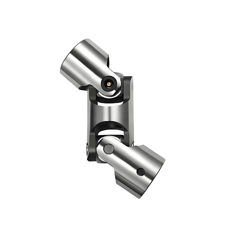 RSK-WS Precision Universal shaft Double type Large-Angle Torque Transmission SupJiangsu Rokang Heavy Industry Technology Co., Ltd is RSK-WS Precision Universal shaft Double type Large-Angle Torque Transmission Supplie...View Product →
Diaphragm Couplings
For torsional stiffness and zero backlash, diaphragm couplings outperform most alternatives. Turbomachinery, test benches, and high-speed pump drives use them because they transmit torque through thin metal discs that flex elastically. On drives running up to 10,000 rpm, a customized high-speed diaphragm coupling rated up to 10,000 rpm avoids lubrication and wear, and the all-metal construction suits high ambient temperatures where elastomeric parts would degrade quickly.
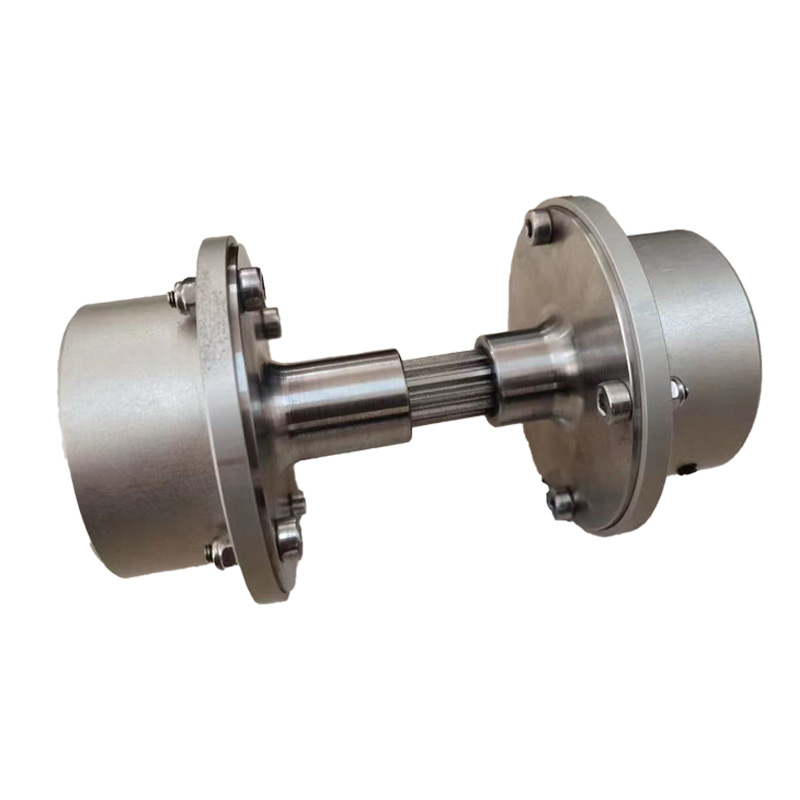 RSK customized high speed diaphragm coupling upto 10000rpm Suppliers, Company -Jiangsu Rokang Heavy Industry Technology Co., Ltd is RSK customized high speed diaphragm coupling upto 10000rpm Suppliers and Wholesale ...View Product →
Elastomeric Couplings
Tire couplings and pin-and-bush couplings add torsional softness and damp vibration. They are economical choices for lower-speed, moderate-torque drives, but their torque density is well below that of gear or diaphragm designs. In heavy equipment, they appear mainly on auxiliary drives and small conveyors where shock absorption matters more than compactness.
A Step-by-Step Sizing Procedure
The procedure below works for most heavy equipment drives, whether you are replacing a failed coupling or designing a new transmission.
- Determine the nominal torque from motor power and operating speed.
- Select the service factor from the machine type, starting frequency, and shock level.
- Calculate the design torque by multiplying the nominal torque by the service factor.
- Verify the peak torque under starting, reversing, or stall conditions.
- Measure the radial, angular, and axial misalignment that the installation actually produces.
- Pick a coupling frame with rated torque above the design torque and misalignment capacity above the measured values.
- Confirm the bore and keyway dimensions against the actual shaft ends.
- Check the maximum speed, and for high-speed or variable-speed drives, perform a torsional vibration analysis.
- Review the environment: temperature range, dust, humidity, and lubrication access.
Common Sizing Mistakes and How to Avoid Them
Most field failures trace back to one of the following mistakes:
- Using motor nameplate torque instead of breakaway or stall torque.
- Choosing too low a service factor for intermittent heavy loads.
- Measuring misalignment only at installation and ignoring thermal growth and foundation settlement.
- Selecting the coupling by bore size alone, without checking the torque rating.
- Oversizing so far that the coupling no longer protects the system from overload.
- Forgetting axial retention when the drive carries high axial thrust.
When the equipment must comply with European practice, the guide to DIN coupling types and selection clarifies how the DIN series compare in torsional stiffness, alignment capacity, and maintenance requirements.
A Practical Sizing Example
Take a belt conveyor driven by a 132 kW electric motor at 1480 rpm, with an 80 mm motor shaft and a gearbox input shaft of the same diameter.
- Nominal torque: Tn = 9550 x 132 / 1480 = 852 Nm.
- Service factor for a conveyor with moderate shock and frequent starts: 1.75.
- Design torque: Td = 852 x 1.75 = 1491 Nm.
- Peak starting torque at 200 percent motor torque: about 1704 Nm.
- Select a coupling frame rated above 1491 Nm, with a maximum bore of at least 80 mm and a keyway that fits the shaft.
A drum gear coupling with a nominal torque rating of 2000 Nm, a maximum bore of 85 mm, and an angular misalignment capacity of about 1.5 degrees would meet the requirement with a reasonable safety margin. The next smaller frame, rated at 1200 Nm, would fail on the design torque check even if its bore fits the shaft. This is why the torque calculation must come before any bore comparison.
Final Checks Before You Place the Order
Before confirming the coupling size, review these points:
- Confirm that the coupling bore matches both the motor shaft and the driven machine shaft.
- Verify the keyway dimensions against the applicable standard.
- Decide whether a brake wheel or brake disc version is required for the application.
- Note the lubrication interval and whether the installation allows easy access for maintenance.
- For high-speed or reversing loads, request a torsional analysis from the manufacturer before finalizing the size.
Sizing shaft couplings for heavy equipment works best as a structured process. Start with the torque, apply an honest service factor, respect the peak conditions, and measure the misalignment that the installation actually creates. When those numbers are correct, the coupling size follows naturally, and the part you install has a realistic chance of lasting as long as the machine it serves.
 Previous