





 English
 русский
 中文简体
中文简体Three disc packs failed in fourteen months on the same 250 kW compressor, and each time the maintenance crew replaced the coupling. The cause was 0.9 mm of axial growth that nobody had budgeted for. After alignment, the pack had less than 0.5 mm of axial capacity left, so every hot start pushed the stainless laminations a little closer to their fatigue limit.
That story carries the conclusion. Flexible disc coupling design is not a torque calculation with a misalignment footnote. It is a search for the narrow band where the coupling is stiff enough to transmit torque without wind-up or backlash, and flexible enough that the forces it feeds back into the bearings, the bolts and its own laminations stay inside their fatigue limits. Design and selection are the same problem, seen from opposite ends of a quotation.
Content
- 1 How a Disc Pack Carries Torque
- 2 Single Disc or Double Disc: A Misalignment Decision
- 3 Stiffness Ratios, Reaction Forces and the Bearing Bill
- 4 Bolts, Balance and the Speed Ceiling
- 5 Materials: Stainless Packs, Steel or Aluminium Hubs
- 6 Site Tolerances: Where a Good Design Becomes a Bad Installation
- 7 Failure Modes Worth Designing Against
- 8 A Practical Selection Sequence
- 9 What Belongs in the Enquiry
How a Disc Pack Carries Torque
A disc pack is a stack of thin stainless steel sheets, typically 0.2 mm to 0.5 mm thick, punched with six to twelve links arranged around the bolt circle. Each sheet is fastened alternately to the two hubs by fitted bolts, so torque travels through the links as tension on one side of the coupling and compression on the other. Misalignment is absorbed only by the sheets bending. Nothing slides, nothing is lubricated, and nothing is made of rubber.
That single fact explains the whole character of the design: zero backlash, no wear surfaces, no elastomer to age or harden, and a temperature ceiling set by the hubs rather than by the flexible element. It also explains the weakness. A coupling with no sliding interface and almost no damping has very little ability to dissipate energy, so whatever stress the links see, they see on every revolution, for the whole life of the machine.
The link profile is the first real design decision. A straight-sided link concentrates bending stress around the bolt holes. A scalloped or waisted link spreads the curvature along its length: flexibility rises, peak stress at the hole falls, and the reaction force the pack pushes back into the bearings at a given misalignment drops with it. The price is torque density, because a scalloped sheet carries less torque per millimetre of width than a straight one, and the pack must recover that with more layers, more bolts or more diameter. Sheet thickness, layer count, link width and bolt count are the four variables that decide what the finished coupling can do.
Single Disc or Double Disc: A Misalignment Decision
Once the pack is defined, the question is how many packs the coupling needs. A single-disc unit places one pack between two hubs. It handles angular and axial displacement comfortably and parallel offset poorly, which suits short, close-coupled drives: servo axes, small pumps, and test rigs where both shafts already sit within a few hundredths of a millimetre.
A double-disc coupling inserts a spacer between two packs. The spacer converts parallel offset into angular displacement at each pack, which is what allows a motor and a gearbox on separate baseplates to be connected without fighting each other. Spacer length then becomes a genuine design variable: it sets how much parallel offset the coupling can absorb, how much it weighs, and how much its own mass and bending behaviour affect the driveline.
| Configuration | Misalignment handled | Typical spacer | Where it fits |
|---|---|---|---|
| Single disc, no spacer | Angular 0.5 to 1 degree, axial, minimal parallel | None | Servo axes, close-coupled pumps, test benches |
| Double disc, short spacer | Angular plus parallel offset in a compact envelope | 50 to 150 mm | General industrial drives, small compressors |
| Double disc, long spacer | Large parallel offset and wide temperature swings | 150 mm and above | Long-span pump and fan drives, hot machinery |
Compact double-disc designs with short spacers and clamp-type hubs are common where the envelope is tight but parallel offset still has to be absorbed, as in machine-tool and CNC drives.
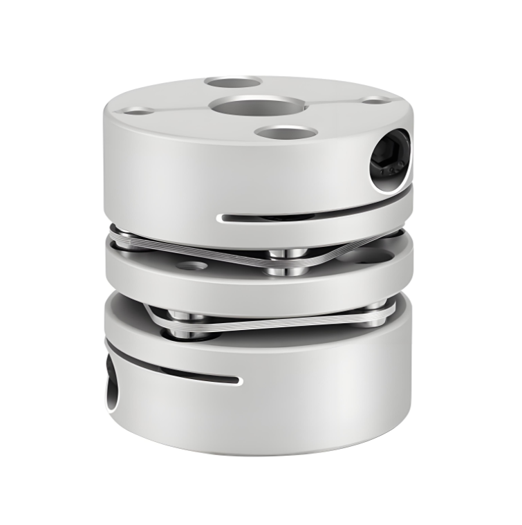 RSK-CPLF Flexible Aluminum Alloy Double Diaphragm Clamp CouplingCompact double-diaphragm clamp coupling for CNC, servo, and stepper drives, with aluminum alloy hubs, 304 stainless diaphragms, high rigidity, low inertia, and backlash-free transmission.View Product →
Stiffness Ratios, Reaction Forces and the Bearing Bill
Torque rating decides whether the coupling survives. Stiffness decides whether everything around it survives. Take the axial case, which is the one most often ignored at the quotation stage. Suppose the coupling you need has an axial stiffness of about 250 N/mm, a realistic figure for a mid-size disc pack, and the shaft grows 0.8 mm between a cold start and full load. The pack will push roughly 200 N back into the bearing, continuously, in addition to the normal bearing load. On a small motor this is enough to shorten bearing life from years to months, and no torque calculation will ever reveal it.
Torsional stiffness works in the opposite direction. It is quoted in Nm per radian or per degree, and the higher it is, the more precisely the driven shaft follows the motor. For positioning axes, high torsional stiffness together with zero backlash is the reason a disc coupling is chosen at all. For a driveline that must pass through a torsional resonance during run-up, that same stiffness is a liability, and low damping makes the peak sharper. If the application involves large motors, reciprocating loads or variable-speed operation, the coupling stiffness belongs in the torsional model rather than in a footnote.
The practical rule: ask the supplier for torsional, axial and radial stiffness values with the quotation, not just the torque rating and the bore size. You cannot check a bearing load or a resonance with a torque figure alone.
Bolts, Balance and the Speed Ceiling
The bolted joint is the part of the design that field experience punishes first. Fitted bolts are ground to a controlled clearance in reamed holes so that torque is carried by the bolt shank in shear rather than by friction between the laminations. That means the fit class matters, and so does the locking method, because a loosened bolt changes the load distribution across the entire pack in a single start.
Speed is the other ceiling, and it is not linear. Residual imbalance force grows with the square of rotational speed: about 1 g-mm of imbalance produces roughly 1.1 N of rotating force at 10,000 rpm, and roughly 4.4 N at 20,000 rpm. Balance quality follows the same logic. General industrial drives are usually acceptable at G6.3, high-speed and machine-tool drives normally call for G2.5, and very high speed or very light rotors may need G1. Above the coupling's rated speed, no amount of balancing helps, because the limit comes from centrifugal stress in the disc pack itself. Where the duty point sits close to that ceiling, a purpose-built high-speed design is the only sensible answer.
Materials: Stainless Packs, Steel or Aluminium Hubs
The disc pack is almost always austenitic stainless steel, with 301 and 302 being the common choices because of their combination of fatigue strength and corrosion resistance. Precipitation-hardening grades such as 17-4 PH appear where higher strength or higher temperature capability is required. The hub is where material choice follows the application. Aluminium alloy hubs in 6061 or 7075 keep inertia low, which matters on servo axes where every gram of rotating mass adds to the motor sizing. Steel hubs in 1045 or an alloy grade, often with black oxide treatment, dominate heavy industrial and long-span drives, and stainless hubs are used where washdown or marine atmosphere is present.
Hub-to-shaft connection deserves more attention than it usually gets. A keyed connection introduces backlash that no zero-backlash disc pack can compensate for, so clamp-type hubs and keyless locking assemblies are the normal specification on positioning and high-reverse drives. Environment, rather than load, decides the surface treatment: blackening for mildly corrosive indoor plant, stainless or plated hardware for outdoor and marine duty.
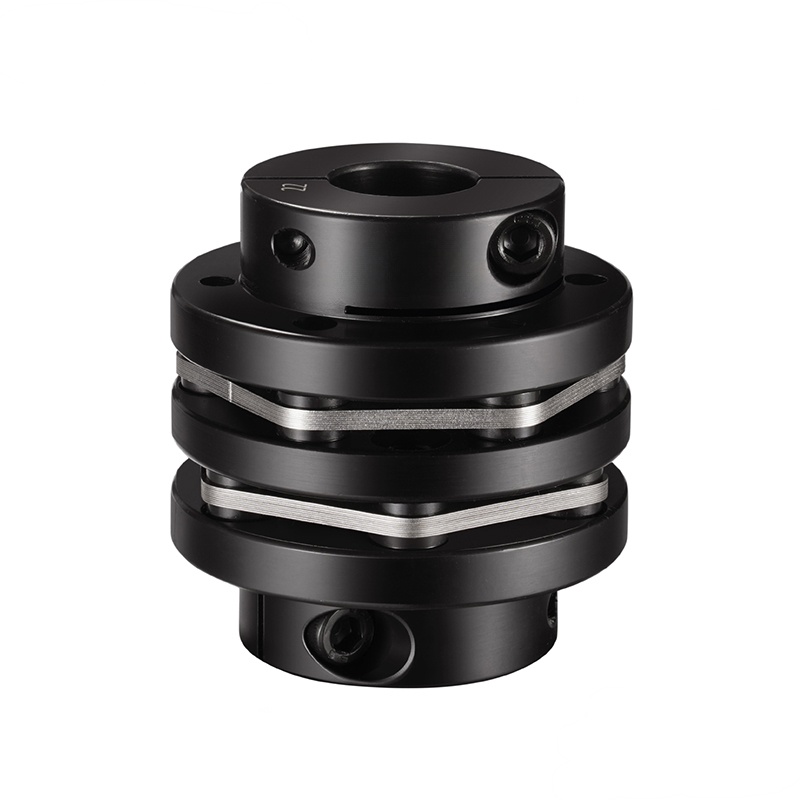 RSK-CPNLT Blackened Stepped Double Diaphragm Clamp CouplingCorrosion-resistant blackened coupling for servo and stepper drives, with keyway, 304 stainless diaphragms, 45# steel hubs, clamp screws, and high torque rigidity.View Product →
Site Tolerances: Where a Good Design Becomes a Bad Installation
Field alignment turns a correct design into an incorrect installation more often than any other single cause. Common targets for a disc coupling are an angular error below 0.5 degrees and an axial setting within 0.5 to 1.5 mm, but those numbers belong to the specific size and pack, so they should come from the supplier's data sheet rather than from habit. Alignment should be checked cold and, where the machine runs hot, verified again at operating temperature, because a shaft that grows 2 mm in a 100 mm span can consume the entire axial allowance of a coupling that was perfectly aligned on the bench.
Two habits cause disproportionate damage. The first is using the coupling bolts to pull two shafts together, which preloads the pack axially before the machine has even started. The second is measuring only the angular error and ignoring parallel offset on a double-disc unit, where the spacer magnifies it into angular displacement at both packs. On drop-out spacer designs, the spacer also has to be supported during assembly so that its weight does not bend the packs before the bolts are torqued.
Failure Modes Worth Designing Against
Most in-service failures trace back to a small number of recognisable patterns:
- Fatigue cracks radiating from the bolt holes in the disc links, almost always the result of sustained misalignment above the rating rather than of overload.
- Fretting and hole elongation, caused by micro-movement at a joint whose preload has been lost.
- Loose or missing locknuts after a rebuild, which redistributes load across the remaining bolts.
- Hub bore slip on the shaft, from an incorrect fit or from a keyed connection that was assumed to be tight enough.
- Corrosion pitting or stress corrosion cracking in washdown, coastal or chemical atmospheres.
- Torsional resonance excited by twice-line-frequency torque ripple, blade-pass frequencies or gear mesh frequencies, where the coupling stiffness was never entered into the driveline model.
A Practical Selection Sequence
A workable order of operations, whether you are designing a coupling or buying one:
- Calculate the continuous torque from power and speed: torque in Nm equals 9550 times power in kW divided by speed in rpm.
- Apply a service factor that reflects the driven machine, typically 1.5 to 2 for smooth loads and 2.5 or more for reciprocating or high-impact duty.
- Check starting, braking and stall torques against the peak rating, not the continuous one.
- Fix the operating speed, then choose the balance grade the speed actually demands.
- Establish the real misalignment: angular, parallel and axial, cold and hot, including manufacturing tolerances between the two machines.
- Convert misalignment into reaction force using the coupling stiffness, and add it to the bearing load.
- Confirm bore, hub type, keyway or clamp connection, spacer length and the available envelope.
- Confirm environment: temperature, moisture, chemicals and washdown frequency.
What Belongs in the Enquiry
A supplier who asks only for bore and torque has not understood your drive, and the quotation that comes back will be a catalogue number rather than a solution. Send continuous and peak torque, speed and duty cycle, all three misalignment components, ambient and operating temperature, corrosion exposure, available envelope, bore and connection type, and the balance grade if the speed is high. Those eight items are the difference between a coupling that quietly outlasts the bearings beside it and one that becomes a scheduled consumable.
If the same plant runs several coupling types, from servo diaphragm units through to heavy gear couplings, a general selection reference covering DIN coupling types and standards is a useful companion to a single quotation, because it makes the comparison between candidate designs concrete instead of verbal.
 Previous