





 English
 русский
When a conveyor drive starts humming instead of clattering, or a pump gearbox carries a heavy load without vibration problems, the helical gearbox is often the reason. For engineers and maintenance teams working with industrial drivetrains, the choice between a helical gearbox and a spur gear unit is rarely just about price—it directly affects noise levels, power density, service life, and downstream component wear. This guide explains how helical gears work, where they outperform other gear types, and the often-overlooked step of selecting a suitable coupling for the gearbox output shaft.
Content
- 1 What Is a Helical Gearbox?
- 2 How Do Helical Gears Work?
- 3 Helical Gearbox vs. Spur Gearbox: Key Differences
- 4 Key Design Types of Helical Gearboxes
- 5 Typical Industrial Applications of Helical Gearboxes
- 6 Gearbox Output Couplings: What to Consider
- 7 How to Choose a Reliable Helical Gearbox Supplier
- 8 Conclusion
What Is a Helical Gearbox?
A helical gearbox is a power transmission unit that uses helical gears—cylindrical gears with teeth cut at an angle to the axis of rotation—to reduce speed and increase torque between parallel shafts. The gearbox typically consists of a housing, input and output shafts, bearings, and one or more gear stages. The teeth of a helical gear are angled relative to the gear axis, unlike spur gears whose teeth are straight and parallel to the shaft.
This angled tooth design changes the fundamental way load is transferred. A spur gear engages its full tooth width instantly, creating shock loads and noise. A helical gear engages gradually: contact begins at one edge of the tooth and spreads diagonally across the face. That simple geometric difference results in significantly smoother operation, higher load capacity, and quieter running.
It is worth distinguishing between the complete gearbox unit and the gear component itself. A helical gearbox is the assembled device. Helical gears are the individual toothed wheels inside it. Some manufacturers produce only gear components, while others build complete gearboxes or focus on other transmission parts—like coupling elements—that are essential to a gearbox drivetrain.
How Do Helical Gears Work?
The angled teeth on a helical gear are defined by the helix angle, typically between 15° and 30°. When two helical gears mesh, they must have the same helix angle but opposite hand—one right-hand and one left-hand. This arrangement ensures the teeth mesh correctly along the line of action. The gradual contact pattern means that at any given moment, multiple teeth are engaged simultaneously. This distributes the transmitted load across several teeth, reducing the stress on individual tooth surfaces and allowing the gear pair to carry higher torque than a comparably sized spur gear set.
The trade-off is the generation of axial thrust. Because the teeth are angled, the contact force has a component acting along the shaft axis. This axial load must be managed with thrust bearings, or by using double helical (herringbone) gears where opposing helix angles cancel the axial force. For most industrial gearboxes, properly sized thrust bearings handle this without difficulty. The efficiency of a helical gearbox is genuinely high—typical values fall between 94% and 98%. The upper end is achievable with well-lubricated, precision-ground gears running at optimal speeds. Gear ratio ranges are equally broad, from a modest 1:3 up to 1:22,000 in multi-stage units.
Helical Gearbox vs. Spur Gearbox: Key Differences
Choosing between a helical and a spur gearbox depends on what matters most for your specific application. The differences are practical, not theoretical.
- Noise and vibration: Spur gears generate noticeable noise and vibration because of sudden full-width tooth engagement. Helical gears are widely quieter—a key advantage in indoor installations or noise-sensitive environments like food processing plants.
- Load capacity: Helical gears have higher load-carrying capacity due to their larger contact ratio. More teeth in engagement means lower stress per tooth, making helical gearboxes the better option for high-torque or shock-loaded applications.
- Smoothness of operation: The progressive engagement of helical teeth results in smoother torque transmission with less pulsation. This can improve the output quality of the driven machine and reduce cyclic stress on downstream components.
- Efficiency: Both types are efficient, but helical gearboxes generally achieve slightly higher efficiencies (94–98%) under equivalent conditions. The difference is small but can be meaningful in continuous-duty applications.
- Axial thrust: Spur gears generate no axial force, simplifying bearing arrangements. Helical gears produce axial thrust that must be accommodated with appropriate bearings or herringbone designs.
- Cost: Spur gears are cheaper to manufacture. Helical gears require more precise machining and heat treatment, increasing the initial cost of the gearbox.
For applications where noise is a concern, load is substantial, or output smoothness matters, the advantages of helical gears clearly outweigh their slightly higher cost.
Key Design Types of Helical Gearboxes
Helical gearboxes come in several structural configurations. Each suits different installation spaces and torque requirements.
Inline (Coaxial) Helical Gearboxes
In an inline gearbox, the input and output shafts are on the same axis. This makes the unit compact and easy to integrate with a motor. You will commonly see these in conveyor drives and packaging machinery, where space is limited and a direct motor-gearbox coupling is preferred.
Parallel Shaft Helical Gearboxes
Here, the input and output shafts are parallel but offset from each other. This configuration allows for larger reduction ratios and higher torque ratings. Parallel shaft units are common in bulk material handling and industrial mixers, where floor space allows a more elongated layout.
Helical-Bevel Gearboxes
These combine a helical gear stage with a bevel gear stage to provide a 90° output direction. This right-angle design is useful when the driven equipment must be positioned perpendicular to the motor. It is a typical choice for agitators, vertical conveyors, and certain pump drives.
Mounting Options
Regardless of the shaft arrangement, helical gearboxes can be foot-mounted, flange-mounted, or shaft-mounted. Shaft-mounted units fit directly onto the driven machine shaft, which can save significant space. Flange-mounted designs are common where the motor directly bolts to the gearbox input.
Typical Industrial Applications of Helical Gearboxes
Because of their combination of efficiency, low noise, and high load capacity, helical gearboxes are used across nearly all industrial sectors.
- Material handling: Conveyors, bucket elevators, and hoists depend on helical gearboxes for reliable, continuous operation.
- Packaging and food processing: Filling machines, labelers, and sealing units require smooth, quiet operation, which helical gears deliver.
- Pumps and compressors: Water pumps, cooling tower fans, and air compressors benefit from the high efficiency and low vibration of these gearboxes.
- Metallurgy and mining: Roller press feed systems, ore crusher conveyors, and heavy plate handling equipment need the high torque and durability that helical gearboxes provide.
- Cranes and hoisting equipment: Travel and lifting mechanisms on overhead cranes demand gearboxes that handle frequent starts, stops, and heavy shock loads.
These heavy-duty applications—metallurgy, mining, and crane operation—place extreme demands not only on the gearbox itself but also on the connection between the gearbox output shaft and the driven machine. A failure of the shaft coupling can disable an entire production line just as quickly as a gear failure. For insight into the coupling types suited to these severe conditions, review drum gear couplings for heavy industrial drive systems, which are commonly specified in such environments.
Gearbox Output Couplings: What to Consider
The gearbox output shaft does not work in isolation. It transfers torque to the driven machine through a coupling. Selecting the wrong coupling—or overlooking its alignment requirements—is a frequent cause of premature bearing and seal failure on gearboxes. The coupling must handle the rated torque, accommodate inevitable misalignment, and sometimes provide additional functions like braking.
Rated Torque and Service Factor
The first parameter is the coupling's rated torque, which must exceed the maximum torque the gearbox can deliver. Always apply a service factor based on your application's load characteristics. A conveyor with steady load might use a 1.25 service factor, while a crusher with heavy shock loads may require 1.75 or higher. Never size a coupling exactly to the motor or gearbox rating without a service factor.
Bore Size and Shaft Connection
Check the coupling's bore capacity against the gearbox output shaft diameter and the driven shaft diameter. Standard keyway connections are common, but for higher torque or frequent disassembly, consider a keyless locking assembly. Elements like a high-load expansion sleeve with easy disassembly features offer a reliable, backlash-free connection and simplify maintenance.
Misalignment Compensation
In a real installation, perfect alignment is an ideal, not a standard. Shafts experience radial misalignment (parallel offset), angular misalignment, and axial end float from thermal expansion. The coupling must accommodate these deviations without generating excessive reaction forces on the gearbox bearings.
Speed and Dynamic Requirements
For high-speed gearbox outputs (above 3,000 rpm), the coupling must be dynamically balanced and should have low mass. Couplings with high torsional stiffness and low moment of inertia are preferred for servo or test stand applications. A customized high-speed diaphragm coupling up to 10,000 rpm is a suitable example of a torsionally stiff element designed for these conditions.
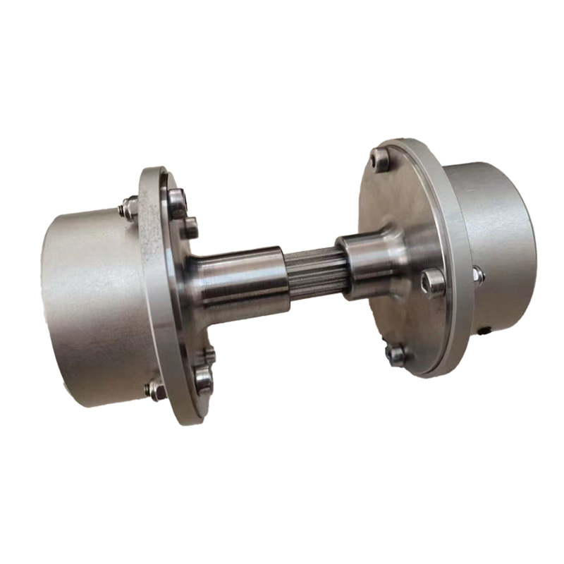 RSK customized high speed diaphragm coupling upto 10000rpm Suppliers, Company -Jiangsu Rokang Heavy Industry Technology Co., Ltd is RSK customized high speed diaphragm coupling upto 10000rpm Suppliers and Wholesale ...View Product →
Braking Requirements
If your driven machine needs dynamic braking, the coupling can incorporate a brake wheel or brake disc. This saves space by combining the connection and braking functions in one unit. In crane travel drives, such integrated units are standard practice.
Coupling Selection by Application
- Gear couplings: For heavy loads and high torque transmission, gear couplings offer high torque density and can accommodate angular misalignment. The wide-type drum gear coupling with high load capacity
 RSK-GICL Drum Gear Coupling Wide Type High load capacity and torque transmissionJiangsu Rokang Heavy Industry Technology Co., Ltd is RSK-GICL Drum Gear Coupling Wide Type High load capacity and torque transmission Sup...View Product → is a go-to choice for severe mill and mining duty. For a broader understanding, review high-performance gear coupling designs and their industrial applications.
 - Diaphragm couplings: These provide high torsional stiffness with zero backlash, making them ideal for high-speed or precision machinery. They also require no lubrication, reducing maintenance.
- Elastic pin couplings: For general industrial duty with moderate shock loads, these couplings provide a degree of damping and are economical to install and maintain.
Standardization is a practical concern. Following recognized standards simplifies spares management and interchangeability. For gearbox output couplings, DIN standards are prevalent. You can compare relevant products in our DIN coupling types, standards, and selection guide. If high-torque transmission with torsional rigidity is non-negotiable, a DIN-standard torsionally rigid gear coupling for high-torque applications is worth examining.
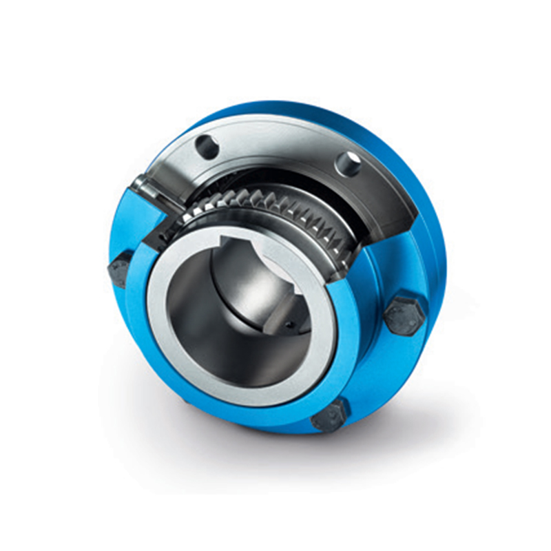 RSK-zapex Series zn-znn type TORSIONALLY RIGID GEAR COUPLINGS High Torque TransmJiangsu Rokang Heavy Industry Technology Co., Ltd is RSK-zapex Series zn-znn type TORSIONALLY RIGID GEAR COUPLINGS High Torque Transmissi...View Product →
Installation and Alignment
Even the best coupling fails if misalignment exceeds its capacity. Use laser alignment tools during installation. For large gear couplings, consider mounting the hubs with the specified interference fit—either thermal shrink-fit or hydraulic mounting. For keyless connections, use the manufacturer's recommended tightening torque on the locking elements to ensure proper torque transmission without fretting.
How to Choose a Reliable Helical Gearbox Supplier
When you are evaluating a supplier for a gearbox or its associated transmission components, technical capability matters more than brochure claims. Assess these factors directly.
- Complete manufacturing capability: A supplier that performs design, precision machining, heat treatment, and fabrication in-house will have better control over quality and lead times than an assembly-only shop.
- Quality inspection systems: Ask about their measurement tools, chemical and physical testing, and dynamic testing capabilities. A manufacturer with a robust internal QC system can substantiate performance claims. Companies like CNRSK (Jiangsu Ronghang Heavy Industry) maintain comprehensive inspection teams covering these areas.
- Relevant industry experience: Experience in heavy industries—steel rolling, mining machinery, crane operation, and marine propulsion—demonstrates that the manufacturer can handle high-stress applications. For example, CNRSK supplies transmission components into these sectors, including metallurgical machinery, metal rolling, and hoisting equipment.
- Customization ability: Standard catalog parts will not always fit your envelope or torque requirement. A reliable partner can engineer a non-standard design—a special shaft length, a unique bore, or a customized brake disc—without compromising on material quality or machining tolerance.
Using a transmission component manufacturer with a full engineering and manufacturing background, like CNRSK, as a benchmark helps ensure your drivetrain has the durability to match the gearbox's design life.
Conclusion
Helical gearboxes provide a strong combination of high efficiency (94–98%), quiet operation, and excellent load-carrying capacity, which is why they dominate modern industrial applications. Understanding the trade-offs with spur gears and the different structural configurations helps you select the right unit for your machine.
Equally important is the connection from the gearbox to your equipment. The output coupling must be selected and installed with as much care as the gearbox itself. Sizing it correctly for torque, allowing for misalignment, and choosing the right coupling type—drum gear, diaphragm, or elastic pin—will prevent many common drivetrain failures. Consulting with an experienced transmission parts manufacturer like CNRSK for coupling advice can bridge the gap between a well-chosen gearbox and a reliable, long-lasting drive system.
 Previous